Supported Interfaces
BlueField BF1600 Controller Card
The BF1600 Controller card is a 9.13 in. x 4.37 in. (232.0 mm x 111.15mm) card. The component height on the top and bottom of the card complies with the PCIe specification. The below figures show the connector and LED designations.
The below figures are for illustration purposes only and might not reflect the current revision of the BF1600 card.
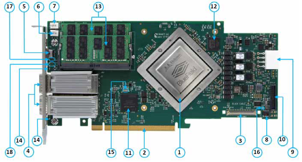
BF1600 Controller Card - Component Side
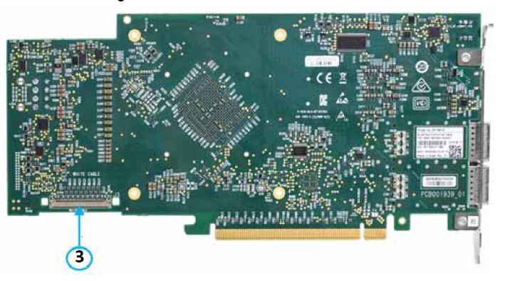
BF1600 Controller Card - Print Side
Callout | Interface | Description |
1 | BlueField SoC with heatsink | |
2 | The interface between the BlueField Controller and the JBOF system. | |
3 | The interface between the PCIe Auxiliary Card and the BlueField Controller Card. | |
4 | Ethernet traffic is transmitted through the controller’s QSFP28 connectors. The QSFP28 connectors allow for the use of Optical modules and cable interconnect solutions. | |
5 | USB Type-B Bracket mounted on card | |
6 | For ConnectX-5 Debug | |
7 | BlueField UART0 (Console): connected to a transceiver and header | |
8 | For Arm debugging | |
9 | Along with the PCIe interface, this connector provides power to the board. | |
10 | Connectivity channel between the BMC CPU and the BlueField Arm Array | |
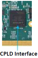
11 | CPLD for board periphery control and power sequencing | |
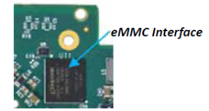
12 | 16GB eMMC Flash memory for software | |
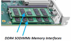
13 | 2 Channel DDR4 SODIMMs, 64bit +ECC | |
SPI Flash for NIC firmware | ||
14 | One bi-color LED per port. | |
15 | Four green LEDs indicating CPLD revision | |
16 | One green LED indicating a proper mating connection to cable | |
17 | One green LED indicating power-good signal | |
18 | 2 bi-color LEDs that indicate proper link status of PCI0 and PCI1 |
PCIe Auxiliary Connection Card
The PCIe Auxiliary Connection card is supplied with the following OPNs: MBF1M626A-CSNAT, MBF1M656A-CSNAT and MBF1M636A-CSNAT.
The PCIe Auxiliary Card is a 5.09in. x 2.32in. (129.30mm x 59.00mm) card. The below figures provide the connector designations.
The below figures are for illustration purposes only and might not reflect the current revision of the BF1600 card.
PCIe Auxiliary Connection Card - Component Side

PCIe Auxiliary Connection Card - Print Side
Callout | Interface | Description |
1 | The interface between the PCIe Auxiliary Card and the JBOF system. | |
2 | The interface between the PCIe Auxiliary Card and the BlueField Controller Card. | |
3 | One green LED indicating proper cable connection | |
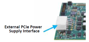
4 | External PCIe Power Supply Interface on the Auxiliary PCIe Connection Card | Connects to the +12V on the PCIe edge connector |
BlueField System On Chip (SoC)
The BF1600 Controller Card is populated with a BlueField SoC. The BlueField IC is a highly integrated System-on-Chip (SoC) optimized for NVMe storage appliances, networking appliances, and programmable networking adapters. BlueField integrates a multicore Arm v8 processor subsystem (sixteen cores) together with a ConnectX®-5 dual-port Virtual Protocol Interconnect (VPI) network controller. The SoC includes two channels of DDR4 DRAM controllers, and 32 lanes of external PCIe lanes supporting Gen3 and Gen 4, along with an embedded PCIe switch.
Ethernet QSFP56 Interfaces
The network ports of the BlueField BF1600 Controller Card are compliant with the IEEE 802.3 Ethernet standards listed in Ethernet traffic is transmitted through the cards' QSFP28 connectors.
QSFP28 Port Over-current Protection
The power consumption for each QSFP28 modules is controlled by a 5W current limiting power distribution switch. Every power limiting switch is controlled by a signal, which is enabled by default. This signal is originated from the thermal shutdown mechanism. When the output load exceeds the current limit threshold, the power switch limits the current to a safe level.
PCI Express Interfaces
The PCI Express bus is a high-speed interface used to connect the Controller Card to other peripheral devices (the BMC, PCIe switch or directly to the NVMe SSDs backplane), and operates as a Root-Complex (RC) initiating PCIe bus operations. The BlueField BF1600 Controller Card supports PCI Express Gen 3.0/4.0 (1.1 and 2.0 compatible) through the following connectors:
PCIe x16 BF1600 Controller Cards:
PCI Express Gen 3.0/4.0 through x16 edge connector
2x PCIe x16 BF1600 Controller Cards:
PCI Express Gen 3.0/4.0 through x16 edge connector
PCIe Express Gen 3.0 through two CABLINE-CA II PLUS x8 connectors - Although these connectors exist on all OPNs, they are functional on PCIe x32 cards used with an Auxiliary Connection Cards.
PCIe x16 Gen 3.0/4.0 Edge Connector
The BF1600 Controller Card supports PCI Express x16 Gen 3.0/4.0 (1.1 and 2.0 compatible) through golden fingers edge connector (separated into Connector A and Connector B) which serves as the main interface of the card. This connector enables the connectivity of the system to the BlueField PCIe interface.
The following lists PCIe interface features:
PCIe Gen 4.0 and 3.0 compliant, 2.0 and 1.1 compatible
2.5, 5.0, or 8.0, or 16.0 GT/s link rate x16
Auto-negotiates to x8, x4, x2, or x1
Support for MSI/MSI-X mechanisms
PCIe Gen 3.0 through Two CABLINE-CA II PLUS Connectors
Applies to MBF1M626A-CSNAT, MBF1M656A-CSNAT and MBF1M636A-CSNAT.
The BlueField BF1600 Controller Card supports PCI Express Gen 3.0 (1.1 and 2.0 compatible) through two on-card x8 CABLINE-CA II PLUS connectors that together provide an additional x16 PCIe interface. The belly to belly CABLINE-CA II PLUS connectors are located on the component and print side of the card and they are connected to the BlueField SoC. The PCIe TX from the system platform (Transmit signals) are connected through the component side CABLINE-CA II PLUS connector, while the PCIe RX from the system platform (Receiving signals) are connected through the print side of the CABLINE-CA II PLUS connector. The connectivity to the NVMe SSDs is allowed through the two CABLINE-CA II PLUS harnesses that are combined to a second x16 PCIe Edge connector mounted on the Auxiliary card.

NCSI Management Interface
The Network Controller Sideband Interface (NCSI) enables the connection of a Baseboard Management Controller (BMC) to a card for the purpose of enabling out-of-band remote manageability. NCSI over the RMII interface is routed through the RMII connector with a flat cable.

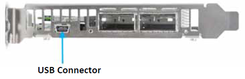
USB Connector
The BlueField BF1600 Controller Card uses a USB 2.0 Type B device. The USB connector is mounted on the Controller Card bracket. The purpose of the USB connector is debugging and loading new versions of the operating systems and firmware.
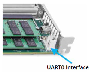
UART0 Interface
The BlueField BF1600 Controller Card provides one Universal Asynchronous Receiver Transmitter (UART0). The UART0 Interface is populated for debugging and bring-up purposes.
I²C0 Interface
The BlueField BF1600 Controller Card provides one I²C0 interface. The I²C0 Interface is populated for ConnectX-5 debug and bring-up purposes.
JTAG CoreSight 10
The BlueField BF1600 Controller Card uses JTAG CoreSight 10-Pin Header. The purpose of the JTAG CoreSight 10 is for debugging the Arm with Arm DSTREAM debug tool. For JTAG CoreSight 10 pins, please refer JTAG CoreSight 10 Interface.
External PCIe Power Supply Interfaces
External PCIe Power Supply Interface on the BF1600 Controller Card
The BF1600 Controller Card requires the +3.3V AUX to come up prior to the +12V at the PCIe connector.
The BlueField BF1600 Controller Card consumes power from two power sources; an external +12V through an 8-pin ATX connector (reference #9) and an additional +12V through the PCIe x16 edge connector. The BF1600 Controller Card’s special circuitry balances the power consumption between these two power sources. Each power source must be capable of supplying up to 75W of power. The delta between both +12V sources must be less than 0.6V for the power-sharing circuit to properly operate. The 3.3V AUX from the card’s PCIe edge connector is used for logics on the BF1600 Controller Card. This logic includes power for buffering logic for signals to the card’s edge connector, power for the FRU EEPROM, and miscellaneous items. The 3.3V from PCIe edge connector is floating on the board. For the external PCIe power supply pins, please refer to External Power Supply Interfaces.
The use of an external power supply interface is restricted to the ATX 8-pin connector only, as shown in the above picture.
External PCIe Power Supply Interface on the Auxiliary PCIe Connection Card
The PCIe Auxiliary Connection card is supplied with the following OPNs: MBF1M626A-CSNAT, MBF1M656A-CSNAT and MBF1M636A-CSNAT
The Auxiliary PCIe card contains the same external +12V power connector as on the BF1600 Controller Card (reference #4). This external +12V connector on the Auxiliary PCIe card connects to the +12V on the PCIe edge connector. It is used for the case where an ATX 8-pin power supply connector is not available in the system. In that situation, it is possible to connect this external +12V connector on the Auxiliary PCIe card to the external +12V connector on the BF1600 Controller card. This allows the BF1600 Controller card to get up to 75W of +12V from its own PCIe edge connector plus up to 75W of +12V from the Auxiliary PCIe card’s edge connector. The Auxiliary PCIe card does not directly use +12V. The Auxiliary PCIe card takes its +3.3V from the PCIe edge connector. The 3.3V AUX rail for the auxiliary card is connected to the EEPROM. For the external PCIe power supply pins, please refer to External Power Supply Interfaces.
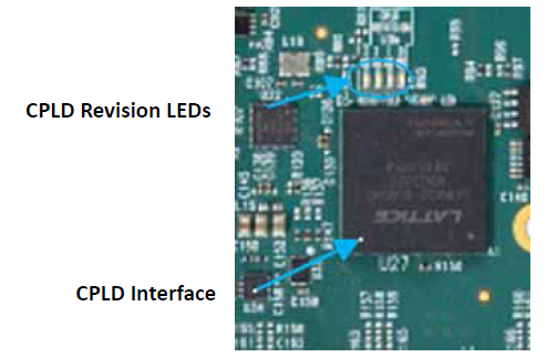
CPLD Interface
The BlueField BF1600 Controller Card incorporates a CPLD device. It drives all BlueField chip configuration pins, all system and device reset, miscellaneous board configuration setups, power monitoring, and power sequence control.
eMMC Interface
The BlueField BF1600 Controller Card incorporates one eMMC (embedded Multi-media Card) interface (eMMC0) which is utilized as a boot source for the Arm core. Arm Tile software (boot, POST, OS code) is stored in eMMC Flash for the boot-load function. The eMMC device size is 16GB.
DDR4 SODIMM Memory
Applies to MBF1M616A-CSNAT, MBF1M636A-CSNAT, MBF1M646A-CSNAT, and MBF1M656A-CSNAT.
The BlueField BF1600 Controller Card incorporates two DDR4 small outline dual-inline memory modules (SODIMM) memory interfaces. Each interface is 16GB, 64-bit data and 8-bit Error Correcting Code (ECC) memory. The connections between the DDR4 SODIMMs and the BlueField SoC is listed in DDR4 DRAM Memory Interface.
The following lists the supported DDR4 data rates:
1600 Mb/s
1866 Mb/s
2133 Mb/s
2400 Mb/s
SPI Flash Memory
The SPI Flash memory is used for storing the NIC firmware as of the ConnectX-5 Flash memory. The SPI Flash memory size is 128Mb.
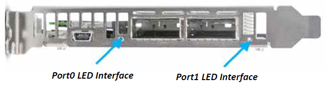
Networking LED Interfaces
There is a one bi-color I/O LED per port to indicate link status. See the below figure for the networking LEDs locations on the BF1600 Controller Card bracket. For LED specifications, please refer to Networking LED Interfaces.
CPLD Revision LEDs Interface
There are four green I/O LEDs to indicate CPLD revision located on the BlueField BF1600 Controller Card. See the below figure for the CPLD LEDs location on the card. For LEDs specifications, please refer to CPLD Revision LEDs Interface.
CABLINE-CA II PLUS Connector LED Interfaces
There is one green I/O LED near each CABLINE-CA II PLUS connector (four LEDs in total) on both on the Controller card and PCIe Auxiliary Connection card indicating the successful connection of the CABLINE-CA II PLUS cables. See the below figure for the green I/O LED location on the cards. For LED specifications, please refer to CABLINE-CA II PLUS Connector LED Interfaces.
Power-Good Signal LED Interface
There is one green I/O LED to indicate power-good signal. See the below figure for LED locations on the card. For the power-good LED specifications, please refer to Power-Good Signal LED Interface.

PCI Link Status LEDs
PCI link status LEDs will be activated in a future revision of the card.
There are two bi-color IO LEDs to indicate proper PCI link status. See the below figure for the location of the LED.
