Appendix: Optical Connector and Patch Cable
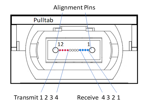
The optical port in the parallel 2x 4-lane optical transceiver is a male MPO connector with alignment pins, mating with fiber-optic cables with female MPO connector. The connector contains a 12-channel MT ferrule.
QSFP28 Optical Male MPO Connector of the Transceiver (front view)
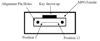
Female MPO Cable Connector

Reference: IEC specification IEC 61754-7.
The fiber which connects transceiver A’s lane 1 must end at transceiver B’s lane 12 at the other end of the link. This calls for a crossed LC cable, also referred to as ‘Type B’.
The fiber is standard single mode fiber. The maximum length is specified in the Operational Specifications section.
LC to LC Patch Cable Fiber Connections
|
Connector A Duplex LC |
Connection |
Connector B Duplex LC |
|
1 |
← |
12 |
|
2 |
← |
11 |
|
3 |
← |
10 |
|
4 |
← |
9 |
|
5 |
Not Connected |
8 |
|
6 |
Not Connected |
7 |
|
7 |
Not Connected |
6 |
|
8 |
Not Connected |
5 |
|
9 |
→ |
4 |
|
10 |
→ |
3 |
|
11 |
→ |
2 |
|
12 |
→ |
1 |
As shown in the above table, the 4 middle positions are not in use, indicating that the cable may have 8 or 12 fibers. Only 8 fibers are used.
The fiber is a standard OM3 or OM4 multi-mode fiber. The maximum length is detailed in the Optical Specifications.
MPO Fiber Patch Cables OM3 (left) and OM4 (right)
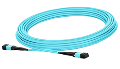
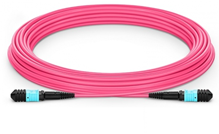
OM4 cables may have aqua or pink colored connectors, depending on the make and model.
NVIDIA does not provide MPO patch cables. Multiple cable vendors provide these patch cables.
Multiple MPO patch cables can be connected in a series, e.g. via Optical Distribution Frames (ODFs). Each added connector pair increases modal dispersion and reflections in the link which impairs performance. An odd number of ‘crosses’ must be used between transceivers at the two ends.