Appendix: Optical Connector and Patch Cable
The optical port in the transceiver is a pair of LC connectors which mate with fiber-optic cables with Duplex-LC UPC connector.
Optical LC Receptacle (transceiver, front view)
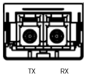
Reference: IEC specification IEC 61754-20.
The fiber which connects transceiver A’s lane 1 must end at transceiver B’s lane 12 at the other end of the link. This calls for a crossed LC cable, also referred to as ‘Type B’. The fiber is standard single mode fiber. The maximum length is specified in the Operational Specifications section.
LC to LC Patch Cable Fiber Connections
|
Connector A Duplex LC |
Connection |
Connector B Duplex LC |
|
1 |
---> |
2 |
|
2 |
<--- |
1 |
Multiple LC patch cables can be connected in series, but each added connector pair adds reflections in the link which again impairs performance. An odd number of ‘crosses’ must be used between transceivers at the two ends.
Typical Look of a Single Mode LC Fiber Patch Cable
