MLAG
A link aggregation group (LAG) is used for extending the bandwidth from a single link to multiple links and provide redundancy in case of link failure. Extending the implementation of the LAG to more than a single device provides yet another level of redundancy that extends from the link level to the node level. This extrapolation of the LAG from single to multiple switches is referred to as multi-chassis link aggregation (MLAG). MLAG is supported on Ethernet blades’ internal and external ports.
Each switch configuration is independent and the user is responsible for configuring both switches similarly pertaining MLAG (e.g., MLAG port-channel VLAN membership, static MAC, ACL, and so forth).
A peered device (host or switch) connecting to switches running an MLAG runs a standard LAG and is unaware of the fact that the LAG connects to two separate switches.
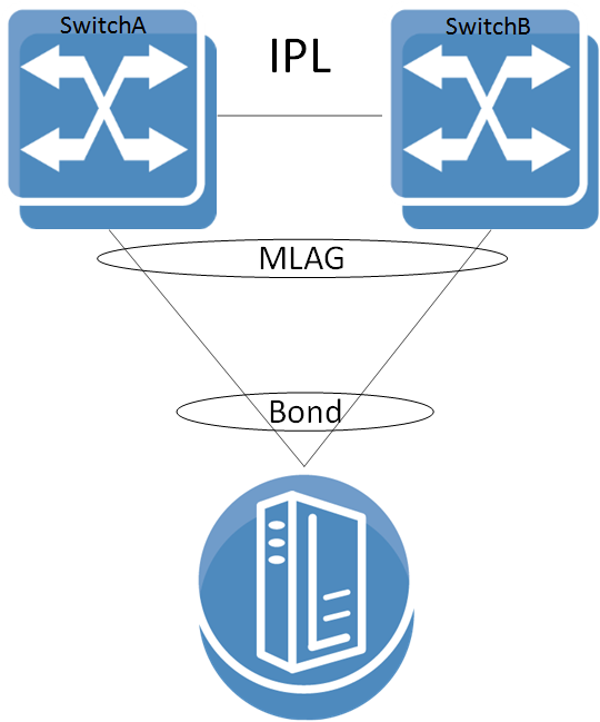
The MLAG switches share an inter-peer link (IPL) between them for carrying control messages in a steady state or data packages in failure scenarios. Thus, the bandwidth of the IPL should be defined accordingly. The IPL itself can be a LAG and may be constructed of links of any supported speed. In such a case, PFC must be configured on this IPL. The figure in section ”Configuring MLAG” illustrates this. The IPL serves the following purposes:
MLAG protocol control: keepalive messages, MAC sync, MLAG port sync, and so forth
MLAG port failure: serves redundancy in case of a fallen link on one of the MLAG switches
Layer-3 failure: serves redundancy in case of a failed connection between the MLAG switches and the rest of the L3 network should there be one
The IPL VLAN interface must be used only for MLAG protocol and must not be used by any other interfaces (e.g., LAG, Ethernet).
Ports 21 and 22 are dedicated IPL ports for MLAG protocol on the SH2200 switch system.
The MLAG protocol is made up of the following components to be expanded later:
Keepalive
Unicast and multicast sync
MLAG port sync
When positioned at the top of rack (ToR) and connecting with a Layer-3 uplink, the MLAG pair acts as the L3 border for the hosts connected to it. To allow default gateway redundancy, both MLAG switches should be addressed by the host via the same default gateway address.
MLAG uses an IP address (VIP) that points to all MLAG member nodes.
When running MLAG as L2/L3 border point, an MAGP VIP must be deployed as the default gateway for MLAG port-channels (MPOs).
When MLAG is connected through a Layer-2 based uplink, there is no need to apply default gateway redundancy towards hosts since this function is implemented on the L2/L3 border points of the network. For more information, refer to the “MAGP” page.
The two peer switches need to carry the exact same configuration of the MLAG attributes for guaranteeing proper functionality of the MLAG.
Ensuring that both switches are configured identically is the responsibility of the user and is not monitored by the OS.
MLAG is currently supported for 2 switches only.
The VIP address must be on the same management IP subnet.
All nodes in an MLAG must be of the same CPU type (e.g., x86), switch type, and must all have the same OS version installed.
When working with MLAG, the maximum number of MAC addresses is limited to 88K. Without it, there is no limitation.
When transitioning from standalone into a group or vice versa, a few seconds are required for the node state to stabilize. During that time, group feature commands (e.g. MLAG commands) should not be executed. To run group features, wait for the CLI prompt to turn into [standalone:master], [<group>:master] or [<group>:standby] instead of [standalone:*unknown*] or [<group>:*unknown*].
Each MLAG VIP group must be configured with a different unicast IP address. If not, MLAG behavior is inconsistent.
In a scenario where there is no IP communication between the MGMT ports of the MLAG switches (for example when one MGMT port is disconnected), the following CLI prompt is displayed: <hostname>[<mlag cluster name>:unknown]#. This does not reflect the MLAG state, but only the state of the cluster.
IPL port-channel should not be configured with LACP rate fast, but should stay with default rate (slow).
Master election in MLAG is based on the IPs of the nodes taking part of the MLAG. The master elected is that which has the highest IPL VLAN interface local IP address.
MLAG master/slave roles take effect in fault scenarios such as split-brain, peer faults, and during software upgrades.
The MLAG pair of switches periodically exchanges a keepalive message on a user configurable interval. If the keepalive message fails to arrive for three consecutive intervals the switches break into two standalone switches. In such a case, the remaining active switch begins to act as a standalone switch and assumes that its previously peering MLAG switch has failed.
To avoid a scenario where failure on the IPL causes both MLAG peers to assume that their peer has failed, a safety mechanism is maintained based on UDP packets running via the management plane which alerts both MLAG switches that its peer is alive. In such case where keepalive packets are not received the slave shuts down its MLAG interfaces and the master becomes a standalone switch in order to avoid misalignment in MLAG configuration.
Unicast and multicast sync is a mechanism which syncs the unicast and multicast FDBs of the MLAG peers. It prevents unicast asymmetric traffic from loading the network with flood traffic and multicast traffic from being processed.
Under normal circumstances, traffic from the IPL cannot pass through the MLAG ports (the IPL is isolated from the MLAG ports). If one of the MLAG links break, the other MLAG switch opens that isolation and allows traffic from its peer through the IPL to flow via the MLAG port which accesses the destination of the fallen link.
A pair of MLAG switches uses a single virtual system MAC for L2 protocols (such as LACP) operating on the MLAG ports. This virtual system MAC is served also as the STP bridge ID.
The virtual system MAC is automatically computed based on the MLAG VIP name, but can be manually set using the command “system-mac”.
MLAG relies on systems to have the same virtual system MAC. Therefore, if a system MAC mismatch is detected, the slave shuts down its interfaces.
Switches in the same MLAG group must have the same OS version.
When peers identify having different versions, they enter an upgrading state in which the slave peer waits for a specific period of time (according to the command “upgrade-timeout”) before closing its ports.
It is advised to plan MLAG upgrade in advance and perform it in a timely manner. Do not perform topology changes during the upgrade period.
From a configuration point of view, to upgrade the MLAG cluster, first upgrade the standby switch and then upgrade the MLAG cluster master (not to be confused with the VIP master).
In the intermediate state where the standby is upgraded and the MLAG cluster master is not, traffic may be impacted by lack of synchronization between the two switches.
By default, there is 60 minutes to upgrade the MLAG cluster master. To avoid traffic impact, shorten the time between upgrading the MLAG standby and upgrading the MLAG cluster master as much as possible.
MLAG cluster master is not to be confused with MLAG VIP master. To see MLAG VIP, run "show mlag-vip". During upgrade, the MLAG VIP master may change based on which switch is up first.
The MLAG cluster master, on the other hand, is the switch with the highest IP address. To see which switch has a higher IP address, run "show mlag"
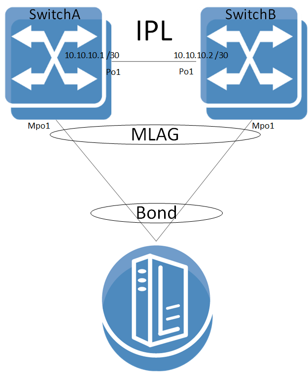
Identify the MLAG cluster master by issuing "show mlag" command. The switch with the higher local IP address of the IPL is the MLAG cluster master (in the example below, SwitchB is the master).
SwitchA [my-vip: master] (config)# show mlag Admin status: Enabled Operational status: Up Reload-delay:
1sec Keepalive-interval:30sec Upgrade-timeout:60min System-mac:00:00:5e:00:01:5d MLAG Ports Configuration Summary: Configured:1Disabled:0Enabled:1MLAG Ports Status Summary: Inactive:0Active-partial:0Active-full:1MLAG IPLs Summary: ID Group Vlan Operational Local Peer Up Time Toggle Counter Port-Channel Interface State IP address IP address ----------------------------------------------------------------------------------------------1Po11Up10.10.10.110.10.10.20days00:00:095Peers state Summary: System-id State Hostname ----------------------------------- F4:52:14:2D:9B:88Up <SwitchA> F4:52:14:2D:9B:08Up SwitchBAfter identifying the MLAG master/standy, make sure to first upgrade the MLAG standby peer according to steps 1-10 in "Upgrading Operating System Software" before upgrading the master.
Wait until the upgraded switch is up and the "show mlag" output looks like the example is step #1, above.
WarningWhen standby MLAG peer upgrade is complete and the master is still in the lower version, MACs are not learned by the standby switch system (except for traffic flood) until master switch upgrade is complete.
Upgrade the MLAG cluster master node according to steps 1-10 in "Upgrading Operating System Software".
When two tiers of MLAG pairs are used, each pair should be upgraded sequentially and not in parallel to prevent traffic loops.
MLAG Interoperability with L2 Protocols
MLAG inter-operates with all STP modes (RSTP, MSTP and PVRST). MLAG can be configured in a spanning tree network where the two MLAG switches function as one STP entity.
In general all static configuration must be configured identically on both peers.
Protocol | Description |
Static MAC addresses | Static MAC address are not synced between MLAG peers |
LACP | MPO supports all LACP modes (passive/active), but it is not a must. If used, their configuration must be identical on each peer. Note: if LACP system-priority is configured on one switch, and not both, it will cause MLAG port-channels to be suspended on one switch. |
VLAN | VLAN membership of an MPO must be configured identically on both peers. This includes PVID, switchport mode, and tagged/untagged VLAN. VLAN static configuration such as snooping MRouter must be configured identically on both peers as well. |
Spanning-tree protocol | MPO spanning-tree configuration must be identical in both switches, and other local ports’ spanning-tree configuration must be done when those ports are down. |
IGMP snooping | IGMP snooping must be activated globally on both peers. IGMP snooping attributes on the MPO must have identical configuration. |
Port mirroring | Supported |
PIM | Not supported |
sFlow | Supported |
LLDP | All attributes of a the MPO must be configured identically on both peers. |
Isolation-groups | Not supported with MLAG |
OpenFlow | Not supported over MLAG IPL |
PTP | Not supported over MLAG IPL (not supported over LAG in general) |
NVE | Not supported |
Dot1x | Not supported |
MLAG Interoperability with Routing Protocols
MLAG can operate with BGP routing protocol. For redundancy purposes, establish BGP session between the two routers over the IPL.
BGP over MPO
To use BGP over MPO, configure the following:
Configure MAGP on the relevant VLAN interface.
Configure IP prefix list, to match all prefixes.
switch(config) # ip prefix-list any seq10permit0.0.0.0/0ge0Configure BGP route map to use MAGP address as nexthop. Advertised next-hop should be the virtual IP address of the MAGP.
switch(config) # route-map magp permit1match ip address anyswitch(config) # route-map magp permit1set ip next-hop <magp-ip-address>Apply BGP route map on neighbor egress direction.
switch(config) # router bgp65000vrfdefaultneighbor <neighbor> route-map magp out
It is not recommended to use OSPF over MLAG port-channel (MPO).
This section provides a basic example of how to configure two switches and a server in an MLAG setup.
For more advanced configuration options, please refer to the community post “MLAG Procedures and Troubleshooting”.
Configuring L2 MLAG
Prerequisites:
Enable IP routing. Run:
switch(config)# ip routing(Recommended) Enable LACP in the switch. Run:
switch(config)# lacpEnable the MLAG protocol commands. Run:
switch(config)# protocol mlag
Configuring the IPL:
Create a VLAN for the inter-peer link (IPL) to run on. Run:
switch(config)# vlan4000switch(config vlan4000)#Create a LAG. Run:
switch(config)#interfaceport-channel1switch(configinterfaceport-channel1)#Map a physical port to the LAG in active mode (LACP). Run:
switch(config)#interfaceethernet1/1channel-group1mode activeSet this LAG as an IPL. Run:
switch(configinterfaceport-channel1)# ipl1Create a VLAN interface. Run:
switch(config)#interfacevlan4000switch(configinterfacevlan4000)#Configure MTU to 9K. Run:
switch(configinterfacevlan4000)# mtu9216Set an IP address and netmask for the VLAN interface.
Configure IP address for the IPL link on both switches:WarningThe IPL IP address should not be part of the management network, it could be any IP address and subnet that is not in use in the network. This address is not advertised outside the switch.
On SwitchA, run:
switch(configinterfacevlan4000)# ip address1.1.1.1/30On SwitchB, run:
switch(configinterfacevlan4000)# ip address1.1.1.2/30WarningThe peer with the interface VLAN with the highest IP is the MLAG master. In the example, above, SwitchB (with IP 1.1.1.2) is the master. The IP addresses of both peers can be seen in via "show mlag" command.
Map the VLAN interface to be used on the IPL and set the peer IP address (the IP address of the IPL port on the second switch) of the IPL peer port. IPL peer ports must be configured on the same netmask.
On SwitchA, run:switch(configinterfacevlan4000)# ipl1peer-address1.1.1.2On SwitchB, run:
switch(configinterfacevlan4000)# ipl1peer-address1.1.1.1(Optional) Configure a virtual IP (VIP) for the MLAG. MLAG VIP is important for retrieving peer information.
WarningIf you have a mgmt0 interface, the IP address should be within the subnet of the management interface. Do not use mgmt1. The management network is used for keepalive messages between the switches. The MLAG domain must be unique name for each MLAG domain. In case you have more than one pair of MLAG switches on the same network, each domain (consist of two switches) should be configured with different name.
On SwitchA, run:
switch(config)# mlag-vip my-vip ip10.234.23.254/24On SwitchB, run:
switch(config)# mlag-vip my-vip(Optional) Configure a virtual system MAC for the MLAG. Run:
switch(config)# mlag system-mac00:00:5e:00:01:5d
Creating an MLAG interface:
Create an MLAG interface for the host. Run:
switch(config)#interfacemlag-port-channel1switch(configinterfacemlag-port-channel1)#WarningThe MPO interfaces should be configured in the same sequence on both switches of MLAG cluster.
Example:
On SwitchA:
interface mlag-port-channel 1-10
interface mlag-port-channel 30-40
On SwitchB:
interface mlag-port-channel 1-10
interface mlag-port-channel 30-40Bind an Ethernet port to the MLAG interface. Run:
switch(configinterfaceethernet1/1)# mlag-channel-group1mode onCreate and enable the MLAG interface. Run:
switch(configinterfacemlag-port-channel1)# no shutdown
Enabling MLAG:
Enable MLAG. Run:
switch(config mlag)# no shutdownWarningWhen running MLAG as L2/L3 border point, MAGP VIP must be deployed as the default GW for MPOs. For more information, refer to “MAGP”.
Verifying MLAG Configuration
Examine MLAG configuration and status. Run show mlag on the switch:
SwitchA [my-vip: master] (config)# show mlag Admin status: Enabled Operational status: Up Reload-delay:
1sec Keepalive-interval:30sec Upgrade-timeout:60min System-mac:00:00:5e:00:01:5d MLAG Ports Configuration Summary: Configured:1Disabled:0Enabled:1MLAG Ports Status Summary: Inactive:0Active-partial:0Active-full:1MLAG IPLs Summary: ID Group Vlan Operational Local Peer Up Time Toggle Counter Port-Channel Interface State IP address IP address ----------------------------------------------------------------------------------------------1Po11Up1.1.1.11.1.1.20days00:00:095Peers state Summary: System-id State Hostname ----------------------------------- F4:52:14:2D:9B:88Up <SwitchA> F4:52:14:2D:9B:08Up SwitchBExamine the MLAG summary table. Run:
SwitchA [my-vip: master] (config) # show interfaces mlag-port-channel summary MLAG Port-Channel Flags: D-Down, U-Up, P-Partial UP, S-suspended by MLAG Port Flags: D: Down P: Up in port-channel (members) S: Suspend in port-channel (members) I: Individual MLAG Port-Channel Summary: ------------------------------------------------------------------------------ Group Type Local Peer Port-Channel Ports Ports (D/U/P/S) (D/P/S/I) (D/P/S/I) ------------------------------------------------------------------------------
1Mpo2(U) Static Eth1/2(P) Eth1/2(P)Examine the MLAG statistics. Run:
SwitchA [my-vip: master] (config)# show mlag statistics IPL
1: Rx Heartbeat :516Tx Heartbeat :516Rx IGMP tunnel :0Tx IGMP tunnel :0RX XSTP tunnel :0TX XSTP tunnel :0RX mlag-notification :0TX mlag-notification :0Rx port-notification :0Tx port-notification :0Rx FDB sync :0Tx FDB sync :0RX LACP manager :1TX LACP manager :0(Optional) In case MLAG-VIP was configured, its functionality can be examined using "show mlag-vip" command.
SwitchA [my-vip: master] (config)# show mlag-vip MLAG VIP ======== MLAG group name: my-mlag-group MLAG VIP address:
10.234.23.254/24Active nodes:2Hostname VIP-State IP Address ---------------------------------------------------- SwitchA master10.234.23.1SwitchB standby10.234.23.2WarningNo output will appear, if MLAG-VIP is not configured.
Enabling L3 Forwarding with User VRF
If you want to use a VRF for IP routing and forwarding on an MLAG topology, it is recommended to configure an additional VLAN interface with the same user VRF context as the non-MLAG L3 interface that has to route through the same physical ports as the IPL. This would allow forwarding L3 traffic through this VLAN interface on the same ports as the IPL.
For more information about this feature and its potential applications, please refer to the following community posts: