Port Mirroring
Port mirroring enables data plane monitoring functionality which allows the user to send an entire traffic stream for testing. Port mirroring sends a copy of packets of a port’s traffic stream, called “mirrored port”, into an analyzer port. Port mirroring is used for network monitoring. It can be used for intrusion detection, security breaches, latency analysis, capacity and performance matters, and protocol analysis.
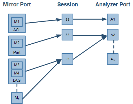
The following figure provides an overview of the mirroring functionality.

There is no limitation on the number of mirroring sources and more than a single source can be mapped to a single analyzer destination.
Port mirroring is performed by configuring mirroring sessions. A session is an association of a mirror port (or more) and an analyzer port.
A mirroring session is a monitoring configuration mode that has the following parameters:
Parameter | Description | Access |
Source interface(s) | List of source interfaces to be mirrored. | RW |
Destination interface | A single analyzer port through which all mirrored traffic egress. | RW |
Header format | The format and encapsulation of the mirrored traffic when sent to analyzer. | RW |
Truncation | Enabling truncation segments each mirrored packet to 64 bytes. | RW |
Congestion control | Controls the behavior of the source port when destination port is congested. | RW |
Admin state | Administrative state of the monitoring session. | RW |
Source Interface
The source interface (mirror port) refers to the interface from which the traffic is monitored. Port mirroring does not affect the switching of the original traffic. The traffic is simply duplicated and sent to the analyzer port. Traffic in any direction (either ingress, egress or both) can be mirrored.
There is no limitation on the number of the source interfaces mapped to a mirroring session.
Ingress and egress traffic flows of a specific source interface can be mapped to two different sessions.
LAG
The source interface can be a physical interface or a LAG.
Port mirroring can be configured on a LAG interface but not on a LAG member. When a port is added to a mirrored LAG it inherits the LAG’s mirror configuration. However, if port mirroring configuration is set on a port, that configuration must be removed prior to adding the port to a LAG interface.
When a port is removed from a LAG, the mirror property is switched off for that port.
Control Protocols
All control protocols captured on the mirror port are forwarded to the analyzer port in addition to their normal treatment. For example LACP, STP, and LLDP are forwarded to the analyzer port in addition to their normal treatment by the CPU.
Exceptions to the behavior above are the packets that are being handled by the MAC layer, such as pause frames.
Destination Interface
The destination interface is an analyzer port to which mirrored traffic is directed. The mirrored packets are duplicated, optionally modified, and sent to the analyzer port. Spectrum platforms support up to only 3 analyzer ports, where any mirror port can be mapped to any analyzer port and more than a single mirror port can be mapped to a single analyzer port.
Packets can be forwarded to any destination using the command "destination interface".
The analyzer port supports status and statistics as any other port.
LAG
The destination interface cannot be a member of LAG when the header format is local.
Control Protocols
The destination interface may also operate in part as a standard port, receiving and sending out non-mirrored traffic. When the header format is configured as a local port, ingress control protocol packets that are received by the local analyzer port get discarded.
Advanced MTU Considerations
The analyzer port, like its counterparts, is subject to MTU configuration. It does not send packets longer than configured.
When the analyzer port sends encapsulated traffic, the analyzer traffic has additional headers and therefore longer frame. The MTU must be configured to support the additional length, otherwise, the packet is truncated to the configured MTU.
The system on the receiving end of the analyzer port must be set to handle the egress traffic. If it is not, it might discard it and indicate this in its statistics (packet too long).
Header Format
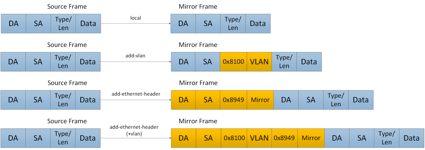
Ingress traffic from the source interface can be manipulated in several ways depending on the network layout using the command header-format.
If the analyzer system is directly connected to the destination interface, then the only parameters that can be configured on the port are the MTU, speed and port based flow control. Priority flow control is not supported is this case. However, if the analyzer system is indirectly connected to the destination interface, there are two options for switching the mirrored data to the analyzer system:
A VLAN tag may be added to the Ethernet header of the mirrored traffic
An Ethernet header can be added with include a new destination address and VLAN tag
It must be taken into account that adding headers increases packet size.
Congestion Control
The destination ports might receive pause frames that lead to congestion in the switch port. In addition, too much traffic directed to the analyzer port (for example 40GbE mirror port is directed into 10GbE analyzer port) might also lead to congestion.
In case of congestion:
When best effort mode is enabled on the analyzer port, Spectrum drops excessive traffic headed to the analyzer port using tail drop mechanism, however, the regular data (mirrored data heading to its original port) does not suffer from a delay or drops due to the analyzer port congestion.
When the best effort mode on the analyzer port is disabled, the Spectrum does not drop the excessive traffic. This might lead to buffer exhaustion and data path packet loss.
The default behavior in congestion situations is to drop any excessive frames that may clog the system.
ETS, PFC and FC configurations do not apply to the destination port.
Truncation
When enabled, the system can truncate the mirrored packets into smaller 64-byte packets (default) which is enough to capture the packets’ L2 and L3 headers.
The size of the original mirrored packet (before adding the encapsulation headers, and including the 4 bytes frame check sequence (FCs)) is truncated to 64 bytes.
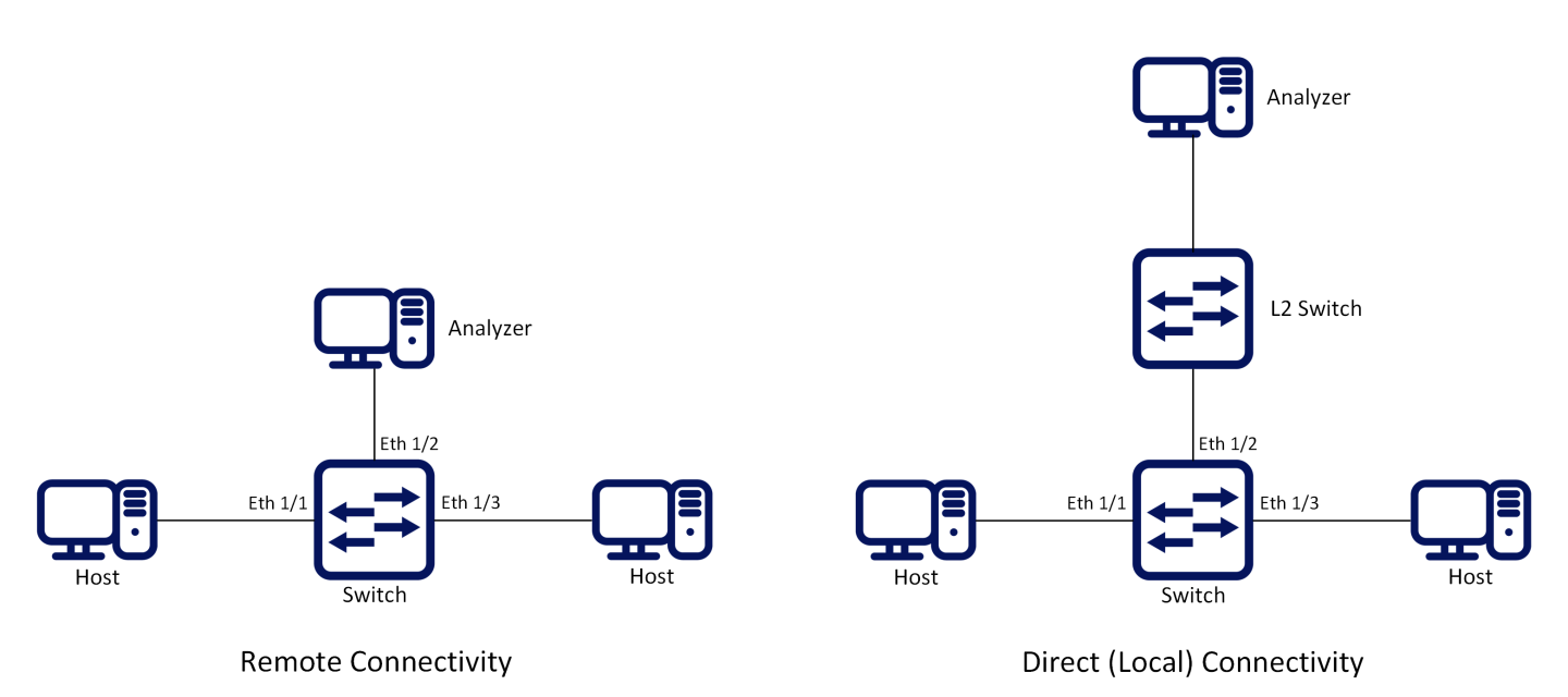
The following figure presents two network scenarios with direct and remote connectivity to the analyzer equipment. Direct connectivity is when the analyzer is connected to the analyzer port of the switch. In this case there is no need for adding an L2 header to the mirrored traffic. Remote connectivity is when the analyzer is indirectly connected to the analyzer port of the switch. In this situation, adding an L2 header may be necessary depending on the network’s setup.
To configure a mirroring session:
Create a session. Run:
switch(config) # monitor session1WarningThis command enters a monitor session configuration mode. Upon first implementation the command also creates the session.
Add source interface(s). Run:
switch(config monitor session1) # add sourceinterfaceethernet1/1direction bothAdd destination interface. Run:
switch(config monitor session1) # destinationinterfaceethernet1/2(Optional) Set header format. Run:
switch(config monitor session1) # header-format add-ethernet-header destination-mac00:0d:ec:f1:a9:c8 add-vlan10priority5WarningFor remote connectivity use the header formats “add-vlan” or “add-ethernet-header”. For local connectivity, use “local”.
(Optional) Truncate the mirrored traffic to 64-byte packets. Run:
switch(config monitor session1) # truncate(Optional) Set congestion control. Run:
switch(config monitor session1) # congestion pause-excessive-framesWarningThe default for this command is to drop excessive frames. The “pause-excessive-frames” parameter uses flow control to regulate the traffic from the source interfaces.
WarningIf the parameter “pause-excessive-frame” is selected, make sure that flow control is enabled on all source interfaces on the ingress direction of the monitoring session using the command “flowcontrol” in the interface configuration mode.
Enable the session. Run:
switch(config monitor session1) # no shutdown
To verify the attributes of a specific mirroring session:
            switch (config) # show monitor session 1
Session 1:
  Admin:  Enable
  Status: Up
  Truncate: Enable
  Destination interface: eth1/2
  Congestion type: pause-excessive-frames
  Header format: add-ethernet-header
  -switch priority: 5

Source interfaces
--------------------
Interface  Direction
--------------------
eth1/1     both
To verify the attributes of running mirroring sessions:
            switch (config) # show monitor session summary
Flags: i ingress, e egress, b both

-------------------------------------------------------------
Session  Admin      Status  Mode       Destination  Source
-------------------------------------------------------------
1        Enable     Up      add-eth    eth1/2       eth1/1(b)
2        Disable    Down    add-vlan   eth1/2       eth1/8(i), po1(e)
3        Enable     Up      add-eth    eth1/5       eth1/18(e)
7        Disable    Down    local
For more information about this feature and its potential applications, please refer to the following community post:
monitor session
monitor session <session-id> Creates session and enters monitor session configuration mode upon using this command for the first time. | ||
Syntax Description | session-id | The monitor session ID |
Default | N/A | |
Configuration Mode | config | |
History | 3.3.3500 | |
3.8.1000 | Updated syntax | |
3.9.1000 | Updated notes and "session-id" range | |
Example | switch (config)# monitor session 1 | |
Related Commands | recirculation | |
Notes |
| |
destination interface
destination interface <type> <number> [force] Sets the egress interface number. | ||
Syntax Description | interface | Sets the interface type and number (e.g. ethernet 1/2) |
force | Eliminates the need to shutdown the port prior to the operation | |
Default | no destination interface | |
Configuration Mode | config monitor session | |
History | 3.3.3500 | |
3.3.4100 | Added force parameter | |
3.6.4006 | Added note | |
Example | switch (config monitor session 1) # destination interface ethernet 1/2 | |
Related Commands | ||
Notes |
| |
shutdown
shutdown Disables the session. | ||
Syntax Description | interface | Sets the interface type and number (e.g. ethernet 1/2) |
force | Eliminates the need to shutdown the port prior to the operation | |
Default | Disabled | |
Configuration Mode | config monitor session | |
History | 3.3.3500 | |
3.3.4100 | Added force parameter | |
3.6.4006 | Added note | |
Example | switch (config monitor session 1) # no shutdown | |
Related Commands | ||
Notes | ||
add source interface direction
add source interface <type> <number> direction <d-type> Adds a source interface to the mirrored session. | ||
Syntax Description | interface | Sets the interface type and number (e.g. ethernet 1/2) |
direction | Configures the direction of the mirrored traffic. The options are as follows:
| |
Default | N/A | |
Configuration Mode | config monitor session | |
History | 3.3.3500 | |
Example | switch (config monitor session 1) # add source interface ethernet 1/1 direction ingress | |
Related Commands | ||
Notes |
| |
header-format
header-format {local [switch-priority <sp>] | add-vlan <vlan-id> [priority <prio>] [switch-priority <sp>] | add-ethernet-header destination-mac <mac-address> [add-vlan <vlan-id> [priority <prio>]] [switch-priority <sp>]} Sets the header format of the mirrored traffic. | ||
Syntax Description | local | The mirrored header of the frame is not changed |
switch-priority | Changes the egress switch priority of the frame | |
add-vlan | An 802.1q VLAN tag is added to the frame | |
priority | The priority to be added to the Ethernet header | |
add-ethernet-header | Adds an Ethernet header to the mirrored frame | |
destination-mac | The destination MAC address of the added Ethernet frame | |
Default | no-change | |
Configuration Mode | config monitor session | |
History | 3.3.3500 | |
3.5.1000 | Added switch-priority parameter | |
3.8.2000 | Updated switch-priority | |
Example | switch (config monitor session 1) # header-format add-ethernet-header destination-mac 00:0d:ec:f1:a9:c8 add-vlan 10 priority 5 switch-priority 2 | |
Related Commands | ||
Notes | If add-ethernet-header is used, the source MAC address is the one of the outgoing Ethernet port. | |
truncate
truncate Truncates the mirrored frames to 64-byte packets. | ||
Syntax Description | N/A | |
Default | no truncate | |
Configuration Mode | config monitor session | |
History | 3.3.3500 | |
3.9.0500 | Added note | |
Example | switch (config monitor session 1) # truncate | |
Related Commands | ||
Notes |
| |
congestion
congestion [drop-excessive-frames | pause-excessive-frames] Sets the system’s behavior when congested. | ||
Syntax Description | drop-excessive-frames | Drops excessive frames |
pause-excessive-frames | Pauses excessive frames | |
Default | drop-excessive-frames | |
Configuration Mode | config monitor session | |
History | 3.3.3500 | |
Example | switch (config monitor session 1) # congestion pause-excessive-frames | |
Related Commands | ||
Notes | This command applies for all sessions on the same analyzer port | |
show monitor session
show monitor session <session-id> Displays monitor session configuration and status. | ||
Syntax Description | session-id | The monitor session ID |
Default | N/A | |
Configuration Mode | Any command mode | |
History | 3.3.3500 | |
3.6.5000 | Updated Example | |
Example | switch (config) # show monitor session 1 Source interfaces | |
Related Commands | ||
Notes | ||
show monitor session summary
show monitor session summary Displays monitor session configuration and status summary. | ||
Syntax Description | session-id | The monitor session ID |
Default | N/A | |
Configuration Mode | Any command mode | |
History | 3.3.3500 | |
3.6.5000 | Updated Example | |
Example | ||
switch (config) # show monitor session summary ------------------------------------------------------------- | ||
Related Commands | ||
Notes | ||