Hardware Installation
Installation of the NVIDIA Skyway gateway requires attention to the mechanical and power elements of the appliance and precautions must be taken for the rack-mounted equipment.
The system platform can be rack-mounted and is designed for installation in a standard 19” rack. The power side of the system includes two hot-swap power supply units (PSUs), and replaceable fan trays. There is one possible airflow direction. It is necessary to validate that the system airflow direction is compatible with the system, rack, and PSUs. The rear panel of the system has the QSFP28 ports, system LEDs, and management connection ports.
Use a rack capable of supporting the mechanical and environmental characteristics of a fully-populated platform.
The rack mounting holes conform to the EIA-310 standard for 19-inch racks. Take precautions to guarantee proper ventilation in order to maintain good airflow at ambient temperature.
The installation procedure of NVIDIA Skyway involves the following steps.
Step | Procedure | Direct Link |
1 | Follow safety warning procedures. | Refer to Safety Warnings |
2 | Pay attention to the system considerations within the host chassis. | Refer to System Requirements |
3 | Follow the safety precautions | Refer to Safety Precautions |
4 | Unpack the package and confirm all required components are present. | Refer to Unpacking the Package |
5 | Mount the appliance in a rack enclosure. | Refer to Rack Mounting |
6 | Use the supplied cables to connect the system | Refer to Cable Installation |
7 | Power on the system. | Refer to Initial Power-On |
Safety Warnings
Prior to the installation, please review the Safety Warnings . Note that some warnings may not apply to all models.
System Requirements
Hardware Requirements
Unless otherwise specified, NVIDIA Networking products are designed to work in an environmentally controlled data center with low levels of gaseous and dust (particulate) contamination.
The operating environment should meet severity level G1 as per ISA 71.04 for gaseous contamination and ISO 14644-1 class 8 for cleanliness level.
Airflow Requirements
NVIDIA Skyway appliance is offered with one airflow pattern: from the front panel to the rear panel.
Refer to the Technical Specifications section for airflow numbers.
Software Requirements
See Operating Systems section under the Introduction section.
Unpacking the Package
Safety Precautions
The NVIDIA Skyway appliance is installed in systems that operate with voltages that can be lethal. Before opening the case of the system, observe the following precautions to avoid injury and prevent damage to system components.
Remove any metallic objects from your hands and wrists.
Make sure to use only insulated tools.
Verify that the system is powered off and is unplugged.
Place the ESD mat on the floor where working and put on the ESD strap. Make sure the ESD strap is touching your skin and that the other end is connected to a verified ground.
System Package Contents
Check the package contents list to see that all the parts have been sent. Check the parts for visible damage that may have occurred during shipping. Please note that the product must be placed on an antistatic surface. Please refer to Package Contents.
The device comes with a key to the front panel. Note that although the key is provided, there is no reason to open the front panel nor to access the elements behind the front panel.
Rack Mounting
The NVIDIA Skyway appliance can be mounted in a rack using the optional rack mounting kit. We strongly recommend that the minimum depth of cabinet is 1100mm.
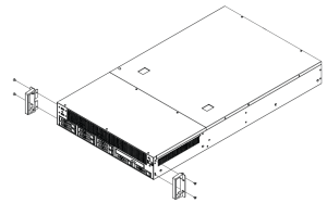
Installing the Server in a Rack
Before mounting the NVIDIA Skyway appliance in a rack, ensure that all internal components have been installed and that the unit has been fully tested. Both sides of the chassis ear must be assembled with screws (PN:1930005209) after the slide rail kit has been assembled.
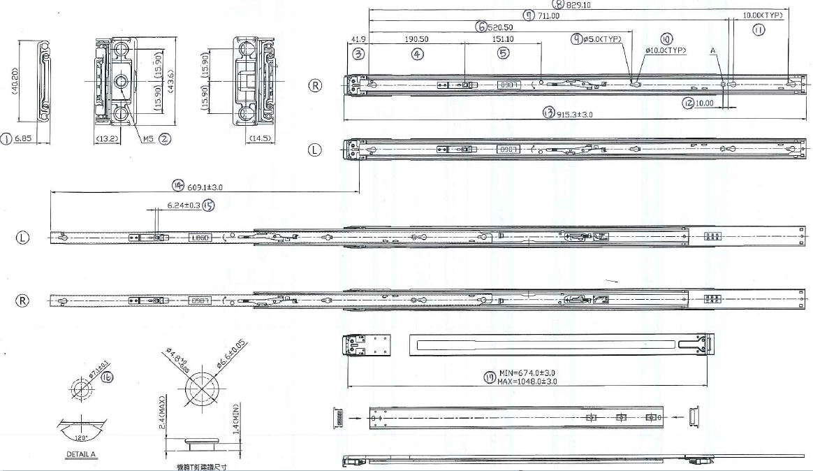
Slide Rail Installation
Read prior to installation.
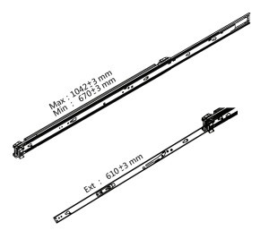
The server slides are developed for 1U or 2U applications of which system load does not exceed 75lbs. The slide length is 1041±3.0mm. The rear bracket is extendable to a max/min post-to-post distance of 670-1042 mm. The slide extension is 610.0±3.0mm.
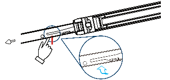
Step 1: Remove inner member. Pull inner member out as in the illustration.
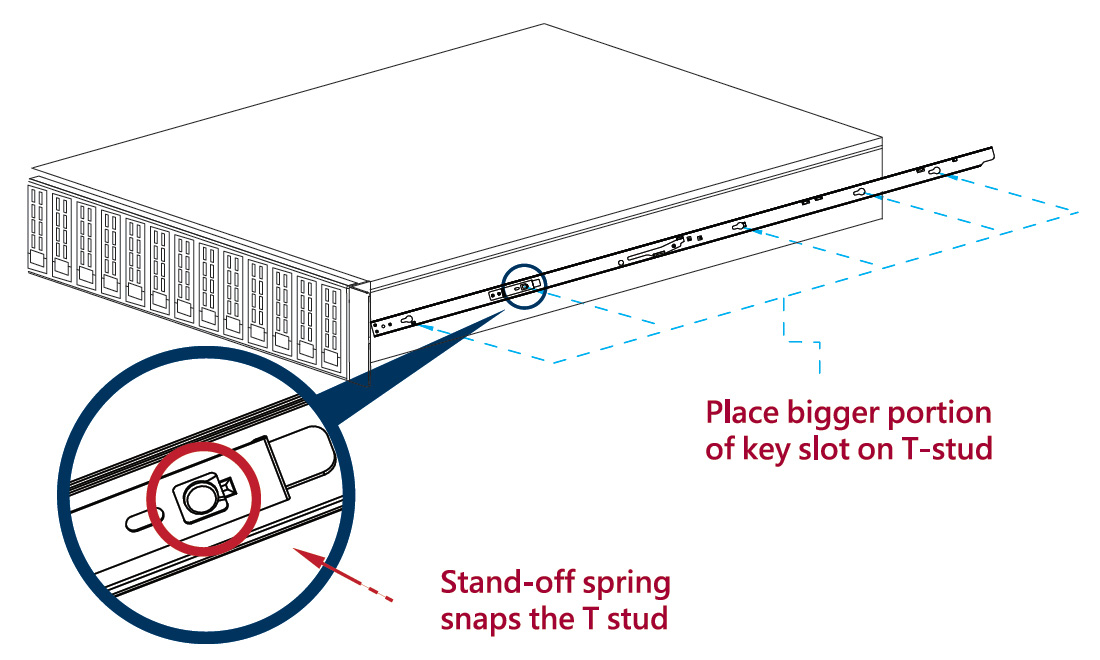
Step 2: Mount the inner member onto the chassis. Place the key slot on T stud, and push the inner member toward the back.
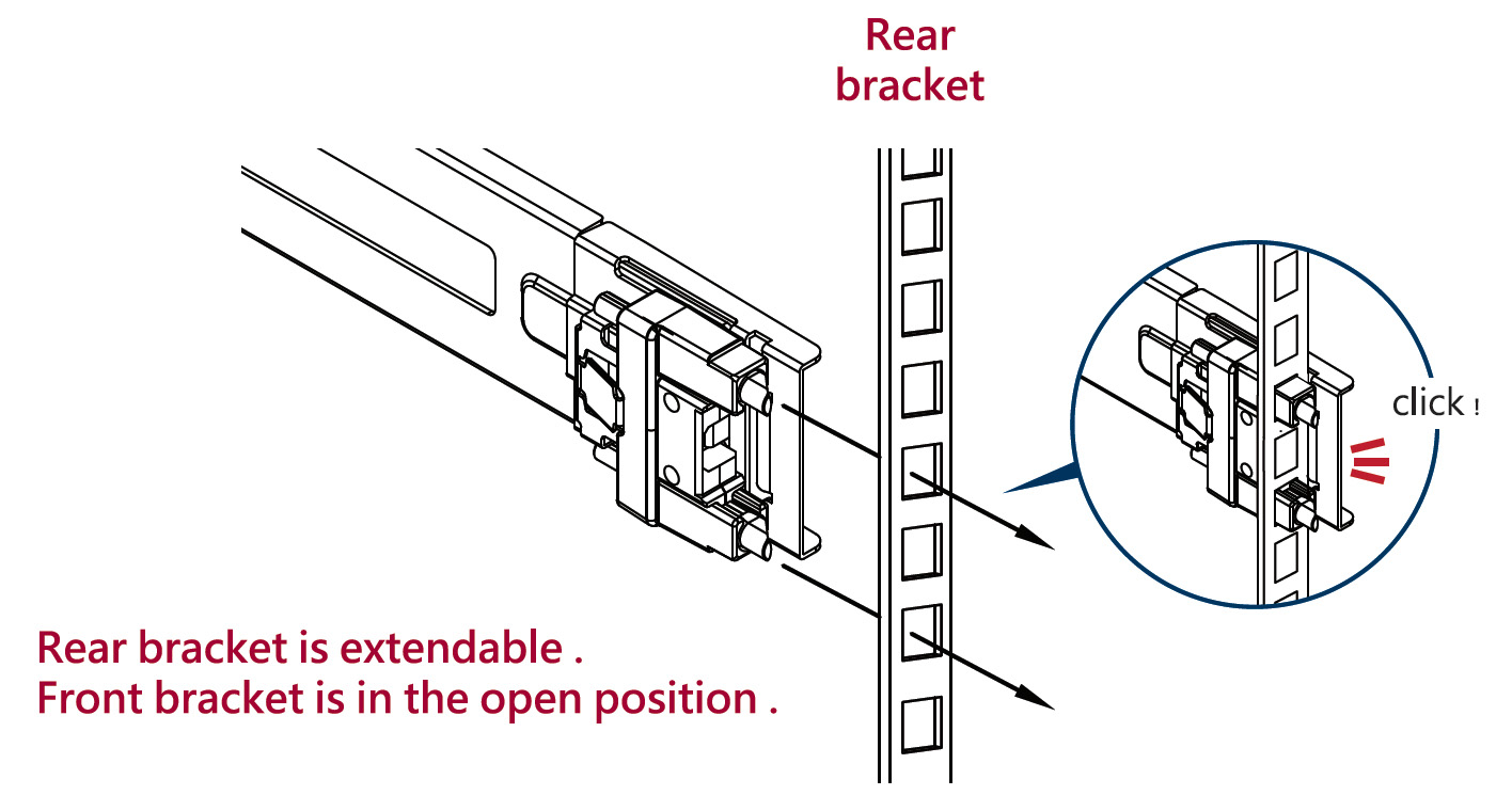
Step 3: Mount the cabinet member to the posts. Align the positioning pin to the desired complete U location, and pull the bracket forwards to lock it to the post. The bracket is locked to the post after a “click” sound is heard.
Step 4: Release the locking latch upward.
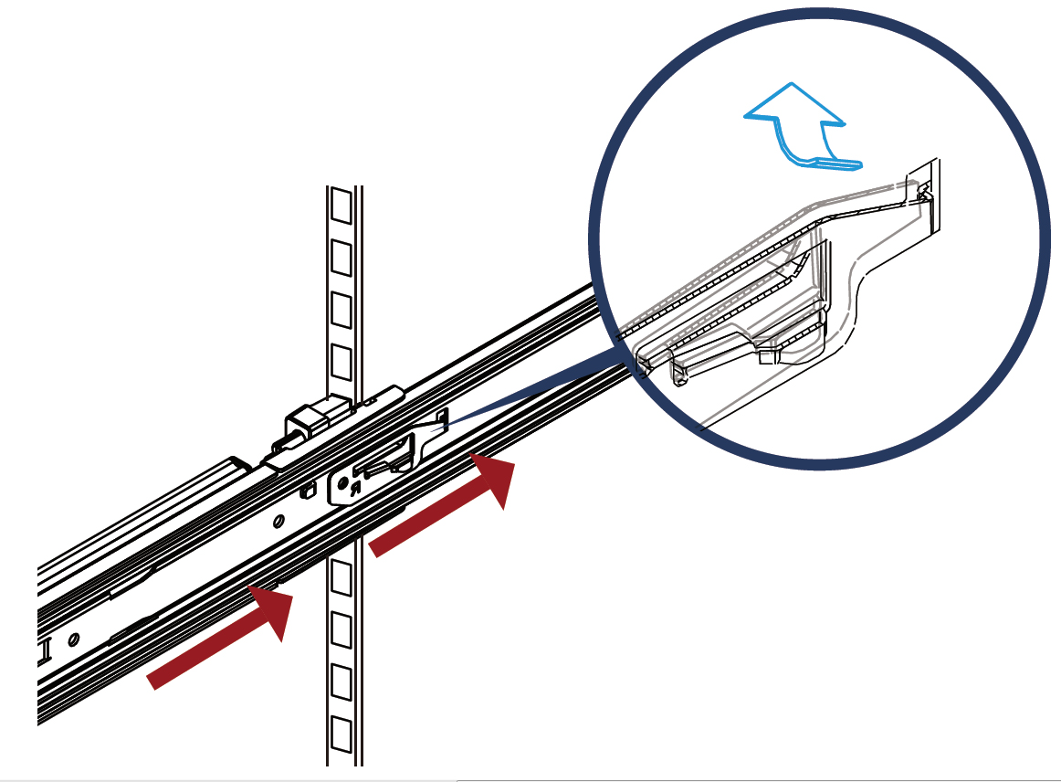
Step 5: Push the middle member forward to the rear of the slide.
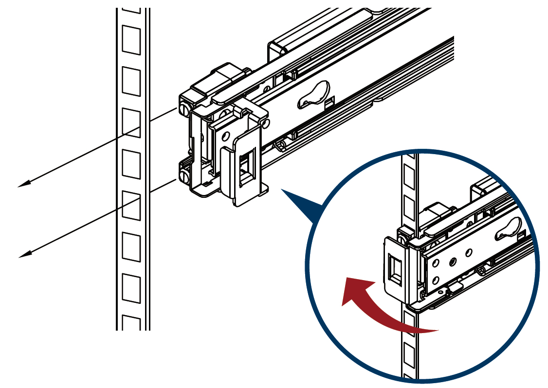
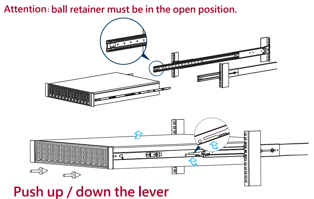
Step 6: Install the chassis.
As shown, insert the inner member to the cabinet member. Make sure the ball retainer is in the open position. If the ball retainer is not on the front position, it might cause damage to the slides. After the inner member goes in, push up/down the disconnect lever to unlock the slides and keep pushing the chassis to the fully-closed position.
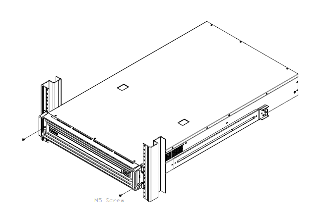
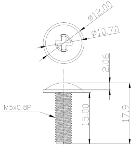
Step 7: Screw the system in the cabinet.
Rack Mount Instructions (similar rack-mount instructions are included with the installation instructions):
Elevated Operating Ambient—If installed in a closed or multi-unit rack assembly, the operating ambient temperature of the rack environment may be greater than the room ambient. Therefore, consideration should be given to installing the equipment in an environment compatible with the maximum ambient temperature (Tma) specified by the manufacturer.
Reduced Air Flow— Installation of the equipment in a rack should be such that the amount of airflow required for the safe operation of the equipment is not compromised.
Mechanical Loading—Mounting of the equipment in the rack should be such that a hazardous condition is not achieved due to uneven mechanical loading.
Circuit Overloading—Consideration should be given to the connection of the equipment to the supply circuit and the effect that overloading of the circuits might have on overcurrent protection and supply wiring. Appropriate consideration of equipment nameplate ratings should be used when addressing this concern.
Reliable Earthing—Reliable earthing of rack-mounted equipment should be maintained. Particular attention should be given to supply connections other than direct connections to the branch circuit (e.g., use of power strips).
Please note that the handlebar and mounting ear must be installed after the slide rail kit has been installed completely.
Power Cable
The NVIDIA Skyway appliance is shipped with two power supply units. Each supply unit has a separate AC receptacle. The appliance accepts voltages of 100-127 VAC and 200-240 VAC for all possible power supply units. The power cords should be a standard 3-wire AC power cards, including a safety ground, and rated for 15A or higher. The power supplies deliver 2KW AC.
After inserting a power cable and turning the appliance on, confirm the green system LED light is on.
Do not hot swap the power supply if your appliance has only one power supply. Instead, power down the system to replace the power supply unit.
ConnectX-6 Networking Cards Cables
To obtain the list of supported NVIDIA Networking cables for the adapter cards, please refer to the Cables Reference Table at http://www.mellanox.com/products/interconnect/cables-configurator.php.
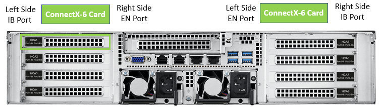
Identifying Ethernet and InfiniBand/VPI Ports
Networking Cable Installation
All cables can be inserted or removed with the unit powered on.
To insert a cable and press the connector into the port receptacle until the connector is firmly seated.
Support the weight of the cable before connecting the cable to the adapter card. Do this by using a cable holder or tying the cable to the rack.
Determine the correct orientation of the connector to the card before inserting the connector. Do not try and insert the connector upside down. This may damage the adapter card.
Insert the connector into the adapter card. Be careful to insert the connector straight into the cage. Do not apply any torque, up or down, to the connector cage in the adapter card.
Make sure that the connector locks in place.
NoteWhen installing cables make sure that the latches engage.
WarningAlways install and remove cables by pushing or pulling the cable and connector in a straight line with the card.
After inserting a cable into a port, the green LED indicator will light when the physical connection is established (that is, when the unit is powered on and a cable is plugged into the port with the other end of the connector plugged into a functioning port). See Network Interface Cards LEDs under the Interfaces section.
After plugging in a cable, lock the connector using the latching mechanism particular to the cable vendor. When data is being transferred, the green LED will blink. See Network Interface Cards LEDs under the Interfaces section.
Care should be taken to not impede the air exhaust flow through the ventilation holes. Use cable lengths that allow for routing horizontally around to the side of the chassis before bending upward or downward in the rack.
To remove a cable, disengage the locks and slowly pull the connector away from the port receptacle. The LED indicator will turn off when the cable is unseated.
All cables can be inserted or removed with the unit powered on. To insert a cable, press the connector into the port receptacle until the connector is firmly seated. The LED indicator, corresponding to each data port, will light up when the physical connection is established. When a logical connection is made, the relevant port LED will turn on. To remove a cable, disengage the locks and slowly pull the connector away from the port receptacle. The LED indicator for that port will turn off when the cable is unseated. For full cabling guidelines, ask your NVIDIA Networking representative for a copy of NVIDIA Cable Management Guidelines and FAQs Application Note.
Do not force the cable into the cage with more than 40 newtons/9.0 pounds/4kg of force. Greater insertion force may cause damage to the cable or to the cage.
This section indicate how the ConnectX-6 IB ports should be physically connected to the IB switches. The below section describes the following topologies:
(e.g. with split-cables, providing 2x HDR100 connections from 2x ConnectX-6(s) to 1 Quantum port).
and what I am missing is like a "zoom in" into the actual Skyway , show how to connect splitter cables from the IB switch to it and how to use regular HDR cables
The system’s input voltage is specified in the Technical Specifications chapter. The power cords should be a standard 3-wire AC power cords including a safety ground and rated for 15A or higher.
The system platform will automatically power on when AC power is applied. There is no power system. Check all boards, power supplies, and fans for proper insertion before plugging in a power cable.
Step 1. Plug in the first power cable.
Step 2. Plug in the second power cable.
Step 3. Wait for the System Status LED to turn green.
It may take up to five minutes to turn on the system. If the System Status LED is red after five minutes, unplug the system and call your NVIDIA Networking representative for assistance.
Step 4. Check the System Status LEDs and confirm that all of the LEDs show status lights consistent with normal operation (initially flashing, and then moving to a steady color). For more information, refer to System Monitoring.
After inserting a power cable and confirming the green System Status LED light is on, make sure that the Fan Status LED is green. If the Fan Status LED is not green, unplug the power connection and check that the fan module is inserted properly and that the mating connector of the fan unit is free of any dirt and/or obstacles. If no obstacles were found and the problem persists, call your NVIDIA Networking representative for assistance.