System Monitoring
Power-On LED
There is one I/O LED (green) on the front panel to indicate if the system is powered.
LED State | Color | Description |
On | Green | System is turned on |
Blinking | Green | System is under S4 state |
Off | N/A | Power off |
LAN Interfaces LEDs
LAN3/LAN4 Rear I/O LED Interface
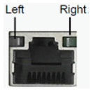
There are two I/O LEDs (green and amber) to indicate LAN link and activity.

Left LED | Right LED | Description |
Off | Green | 10M bps linked |
Off | Blinking Green | 10M bps active |
Amber | Green | 100M bps linked |
Amber | Blinking Green | 100M bps active |
Green | Green | 1G bps linked |
Green | Blinking Green | 1G bps active |
Off | Off | No link |
LAN1/LAN 2 Rear I/O LED Interface
There are two I/O LEDs (green and amber) to indicate LAN link and activity.

Left LED | Right LED | Description |
Amber | Green | 1G bps linked |
Amber | Blinking Green | 1G bps active |
Green | Green | 10G bps linked |
Green | Blinking Green | 10G bps active |
Off | Off | No link |
Power Module LED
There are two I/O LEDs (amber and green) to indicate the power module state.
LED State | Color | Description |
Blinking | Amber | Power supply warning event |
Blinking | Green | AC present standy output on |
On | Amber | AC unplug to this module or power supply critical event |
On | Green | Power supply DC output ON and OK |
Off | Off | No AC power to both power modules |
Network Interface Cards LEDs
There are two I/O LEDs per port:
LED 1 and 2: Bi-color I/O LED which indicates link status. LED behavior is described below for Ethernet and InfiniBand port configurations.
LED 3 and 4: Reserved for future use.

LED1 and LED2 Link Status Indications (Physical and Logical)—Ethernet Protocol
LED Color and State | Description |
Off | A link has not been established. |
Blinking amber | 1 Hz blinking amber occurs when a beacon command for locating the adapter card running . 4 Hz blinking amber indicates a problem with the physical link. |
Solid green | Indicates a valid link with no active traffic. |
Blinking green | Indicates a valid logical link with active traffic. |
LED1 and LED2 Link Status Indications (Physical and Logical)—InfiniBand Protocol
LED Color and State | Description |
Off | A physical link has not been established. |
Solid amber | Indicates an active physical link. |
Blinking amber | 1 Hz blinking amber occurs when a beacon command for locating the adapter card is running. 4 Hz blinking amber indicates a problem with the physical link. |
Solid green | Indicates a valid logical (data activity) link with no active traffic. |
Blinking green | Indicates a valid logical link with active traffic. |