Hardware Installation
Installation of the NVIDIA UFM Cyber-AI appliance requires attention to the mechanical and power elements of the appliance and precautions must be taken for the rack-mounted equipment.
The system platform can be rack-mounted and is designed for installation in a standard 19” rack. The power side of the system includes a hot-swap power supply unit (PSU), space for an optional second PSU (purchased separately) for redundancy, and replaceable fan trays. There is one possible airflow direction. It is necessary to validate that the system airflow direction is compatible with the system, rack, and PSUs. The rear panel of the system has the QSFP28 ports, system LEDs, and management connection ports.
Use a rack capable of supporting the mechanical and environmental characteristics of a fully-populated platform.
The rack mounting holes conform to the EIA-310 standard for 19-inch racks. Take precautions to guarantee proper ventilation in order to maintain good airflow at ambient temperature.
Check against the package contents list that all the parts have been sent. Check the parts for visible damage that may have occurred during shipping. Please note that the product must be placed on an antistatic surface.
Item Type | Qty | Item Description |
System | 1 | UFM Cyber-AI Appliance Gen 4.0 |
Slide Rail Kit | 1 | 1U/2U 36" slide kit pair for UFM Cyber-AI Appliance |
Power Cables | 2 | 250V 10A 1830MM C14 TO C13 power cable |
2 | Cable retainers | |
Harness | 1 | Harness RS232 2m cable – DB9-to-RJ45 Warning
Do not connect to the COM port. |
1 | Ethernet CAT6A 2m cable – RJ45-to-RJ45 | |
Documentation | 1 | Quick installation guide |
Item Type | Qty | Item Description |
System | 1 | UFM Cyber-AI Appliance Gen 4.0 |
Slide Rail Kit | 1 | 1U/2U 36" slide kit pair for UFM Cyber-AI Appliance |
Power Cables | 2 | 250V 10A 1830MM C14 TO C13 power cable |
2 | Cable retainers | |
Harness | 1 | Harness RS232 2m cable – DB9-to-RJ45 Warning
Do not connect to the COM port. |
Ethernet Cable | 1 | Ethernet CAT6A 2m cable – RJ45-to-RJ45 |
Documentation | 1 | Quick installation guide |
Rail Kit Package Contents
Item type | Qty | Item description |
Slides | 2 | Set of rack slides |
Screw M5* 15L | 2 | M5* 15L – 8pcs |
UFM Cyber-AI Appliance can be mounted in a rack using the optional rack mounting kit.
The minimum post-to-post dimension is 890mm.
It is strongly recommended that the minimum depth of cabinet be 1100mm.
Safety Warnings
Prior to the installation, make sure to review the safety warnings. Note that not all warnings may apply to the UFM Cyber-AI Appliance.
Safety warnings are provided here in the English language. For safety warnings in other languages, refer to the 1U Switch Installation Safety Instructions document.

| Installation Instructions Read all installation instructions before connecting the equipment to the power source. |

| Bodily Injury Due to Weight Use enough people to lift this product safely. 
|
|
| Heavy Equipment This heavy equipment should be moved using a mechanical lift to avoid injuries. |

| Risk of Electric Shock!
|
|
| Over-temperature This equipment should not be operated in an area with an ambient temperature exceeding the maximum value listed in the product specifications. Moreover, to guarantee proper ventilation, allow at least 8 cm (3 inches) of clearance around the ventilation openings. |
|
| Stacking the Chassis The chassis should not be stacked on any other equipment. If the chassis falls, it can cause bodily injury and equipment damage. |
|
| Redundant Power Supply Connection (OPTIONAL)—Electrical Hazard This product includes a redundant power or a blank in its place. In case of a blank power supply, do not operate the product with the blank cover removed or not securely fastened. |
|
| Double Pole/Neutral Fusing This system has double pole/neutral fusing. Remove all power cords before opening the cover of this product or touching any internal parts. |
|
| Multiple Power Inlets Risk of electric shock and energy hazard. The PSUs are all independent. Disconnect all power supplies to ensure a powered down state inside of the switch platform. |
|
| During Lightning—Electrical Hazard During periods of lightning activity, do not work on the equipment or connect or disconnect cables. |
|
| Copper Cable Connecting/Disconnecting Copper cables are heavy and not flexible, as such they should be carefully attached to or detached from the connectors. Refer to the cable manufacturer for special warnings/instructions. |
|
| Rack Mounting and Servicing When this product is mounted or serviced in a rack, special precautions must be taken to ensure that the system remains stable. In general, the rack should be filled with equipment starting from the bottom to the top. |
|
| Equipment Installation This equipment should be installed, replaced, and/or serviced only by trained and qualified personnel. |
|
| Equipment Disposal Disposal of this equipment should be in accordance to all national laws and regulations. |
|
| Local and National Electrical Codes This equipment should be installed in compliance with local and national electrical codes. |
|
| Installation Codes This device must be installed according to the latest version of the country national electrical codes. For North America, equipment must be installed in accordance to the applicable requirements in the US National Electrical Code and the Canadian Electrical Code. |
|
| Battery Replacement Warning: Replace only with UL Recognized battery, certified for maximum abnormal charging current not less than 4mA. There is a risk of explosion should the battery be replaced with a battery of an incorrect type. Dispose of used batteries according to the instructions. |
|
| UL Listed and CSA Certified Power Supply Cord For North American power connection, select a power supply cord that is UL Listed and CSA Certified, 3 - conductor, [16 AWG], terminated with a molded plug rated at 125 V, [13 A], with a minimum length of 1.5m [six feet] but no longer than 4.5m. For European connection, select a power supply cord that is internationally harmonized and marked “<HAR>”, 3 - conductor, minimum 1.0 mm2 wire, rated at 300 V, with a PVC insulated jacket. The cord must have a molded plug rated at 250 V, 10 A. |
|
| Installation Codes This device must be installed according to the latest version of the country's national electrical codes. For North America, equipment must be installed in accordance to the applicable requirements in the US National Electrical Code and the Canadian Electrical Code. |
|
| Interconnection of Units Cables for connecting to the unit RS232 and Ethernet Interfaces must be UL certified type DP-1 or DP-2. (Note: when residing in non LPS circuit.) |
|
| Overcurrent Protection A readily accessible Listed branch circuit overcurrent protective device rated 20 A must be incorporated in the building wiring. Acoustic Level Warning The acoustic level listed in Specifications section represents product noise measured in accordance with ISO 7779 under nominal conditions. The actual noise level can vary depending on the installation conditions, including but not limited to the number of racks in the installation, the overall installation size, rack and other equipment material and noise levels, fan faults, room temperature, room configuration, and employee location in relation to the equipment. The data-center owner should manage effective hearing conservation as per the OSHA standard to protect employees against over and extended exposure to noise. |

| Do Not Use the Switch as a Shelf or Work Space Caution: Slide/rail mounted equipment is not to be used as a shelf or a work space. The rails are not intended for sliding the unit away from the rack. It is for permanent installation at final resting place only, not used for service and maintenance. |

| WEEE Directive According to the WEEE Directive 2002/96/EC, all waste electrical and electronic equipment (EEE) should be collected separately and not disposed of with regular household waste. Dispose of this product and all of its parts in a responsible and environmentally-friendly way. |
|
| Country of Norway Power Restrictions This unit is intended for connection to a TN power system and an IT power system of Norway only. |

Taiwan RoHS Declaration - Switch Systems

Taiwan RoHS Declaration - Gateway Systems

Taiwan BSMI Class A Statement - Warning to the User!
警告:為避免電磁干擾,本產品不應安裝或使用於住宅環境。
Installing Appliance in Rack
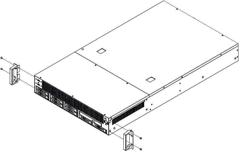
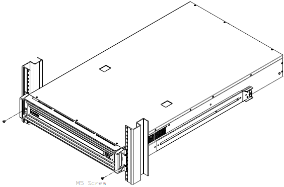
Before mounting UFM Cyber-AI Appliance in a rack, ensure that all internal components are installed, and that the unit has been fully tested. Both sides of the chassis ear must be assembled with screws (PN:1930005209) after you assemble the slide rail kit.
Slide Rail Installation
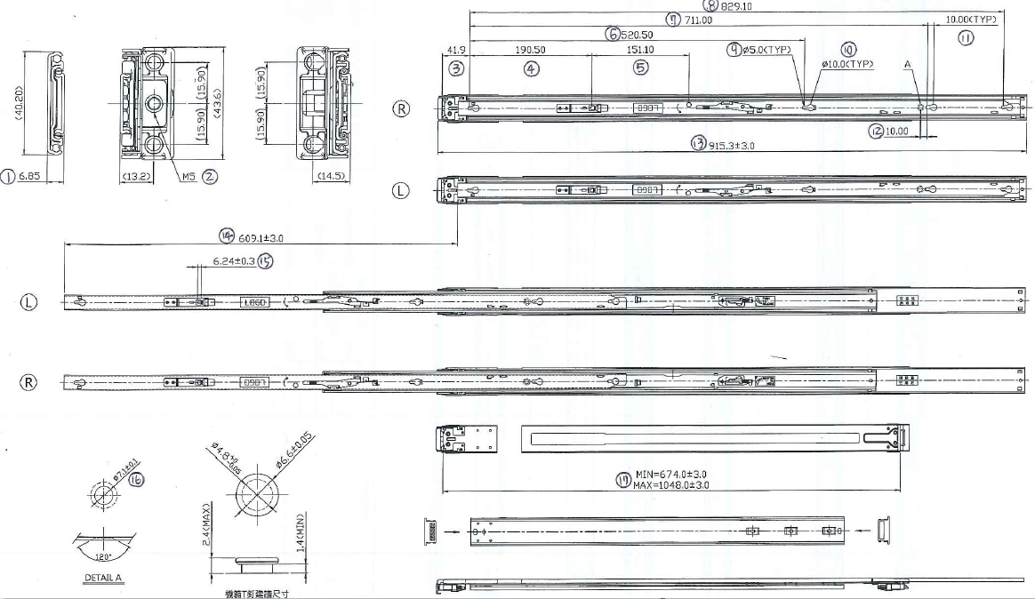
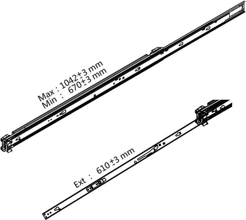
The UFM Cyber-AI Appliance slides are developed for 1U or 2U applications whose system load does not exceed 34 kgs. The slide length is 1041±3.0 mm. The rear bracket is extendable to a max/min post-to-post distance of 670-1042 mm. The slide extension is 610.0±3.0 mm.
Remove the inner member. Pull inner member out as shown in the following figure.
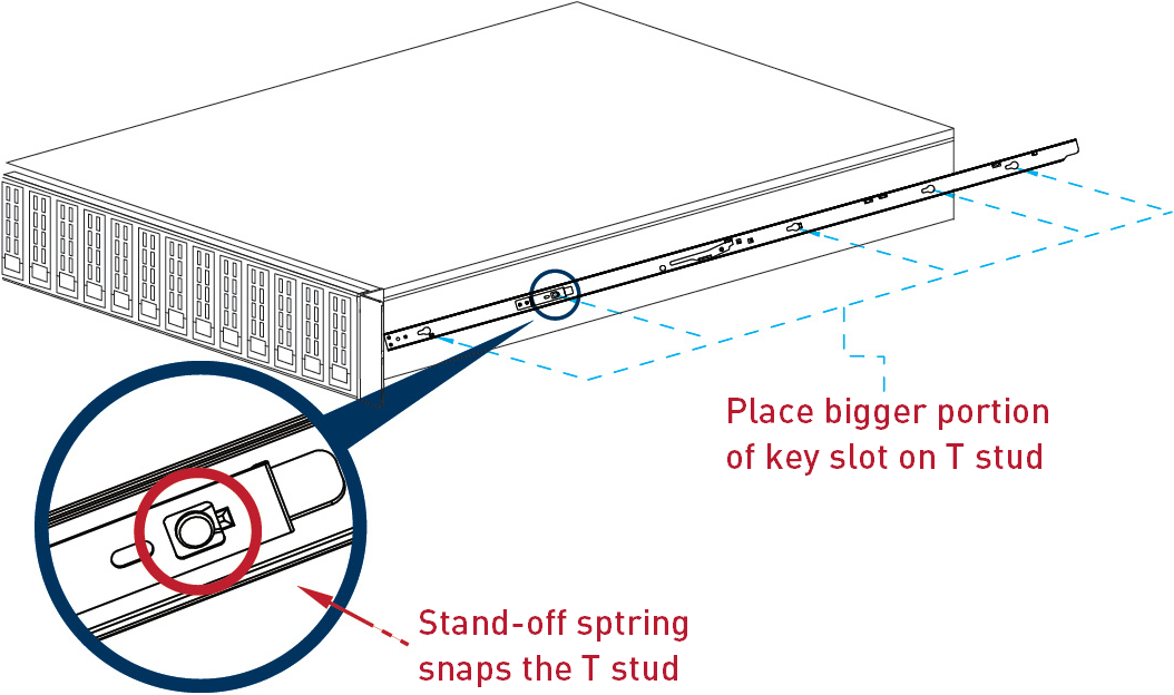
Mount the inner member onto the chassis. Place the key slot on T stud and push the inner member toward the back.
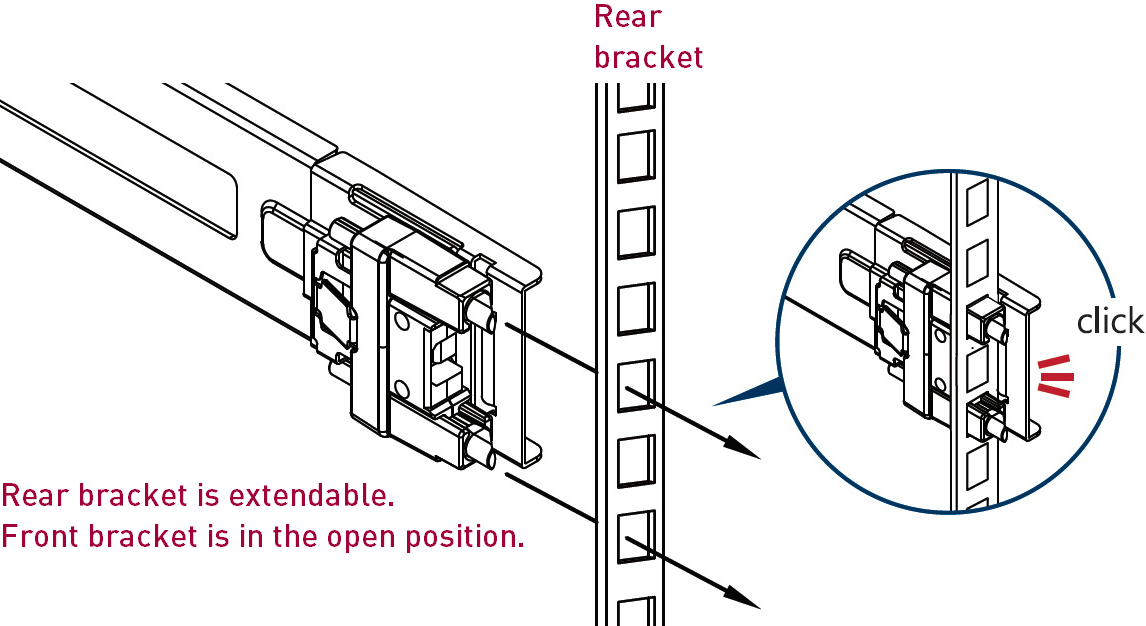
Mount the cabinet member to the posts. Align the positioning pin to the desired complete U location, and pull the bracket forwards to lock it to the post. The bracket is locked to the post after you hear a “click” sound.
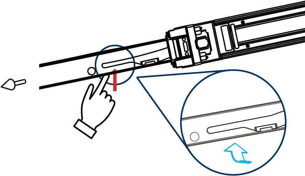
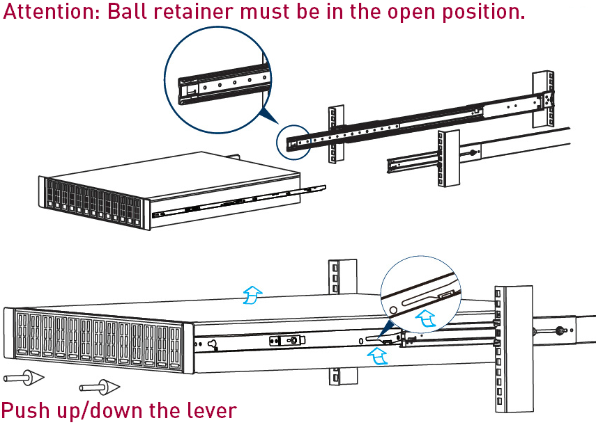
Release the locking latch upward.
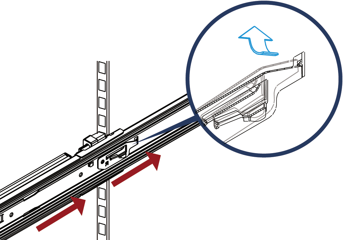
Push the middle member forward to the rear of the slide.
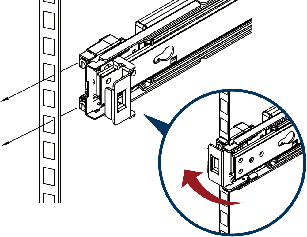
Install the chassis. As shown, insert the inner member to the cabinet member. Make sure the ball retainer is in the open position. It might cause damage to the slides if the ball retainer is not on the front position. After the inner member goes in, push up/down the disconnect lever to unlock the slides and keep pushing the chassis to the fully closed position.
Screw the system in the cabinet.
 Note
NoteThe following or similar rack-mount instructions are included with the installation procedure:
Elevated Operating Ambient – if installed in a closed or multi-unit rack assembly, the operating ambient temperature of the rack environment may be greater than the room ambient. Therefore, consideration should be given to installing the equipment in an environment compatible with the maximum ambient temperature (Tma) specified by the manufacturer.
Reduced Air Flow – installation of the equipment in a rack should be such that the amount of airflow required for the safe operation of the equipment is not compromised.
Mechanical Loading – mounting of the equipment in the rack should be such that a hazardous condition is not achieved due to uneven mechanical loading.
Circuit Overloading – consideration should be given to the connection of the equipment to the supply circuit and the effect that overloading of the circuits might have on overcurrent protection and supply wiring. Appropriate consideration of equipment nameplate ratings should be used when addressing this concern.
Reliable Earthing – reliable earthing of rack-mounted equipment should be maintained. Particular attention should be given to supply connections other than direct connections to the branch circuit (e.g. use of power strips).
Please note that you must install the handlebar and mounting ear after the slide rail kit has been installed completely.