Appendix - Switch Grouping
To facilitate the logical grouping of 1U switches into a "director-like switch" group, the UFM implements a special dedicated group of interconnected 1U switches based on a YAML configuration file. This group, which is of type "superswitch", only includes 1U switches connected to each other, with some functioning as lines and others as spines.
To access the configuration file for superswitches, users can define the path in the [SubnetManager] section of the gv.cfg file, using the variable name "super_switch_config_file_path". For instance, the path can be specified as follows: super_switch_config_file_path=/opt/ufm/files/conf/super_switches_configuration.cfg.
It is important to note that the file must be located in the /opt/ufm/files file tree, as it should be replicated between master and slave UFM servers in a high-availability configuration.
The structure of the superswitch definition should be as follows, based on the following example:
            superswitch:
  - name: "Marlin01" # Director switch name
    description: "primary dc switch" # Free text with the customer facing description
    location: "US, NC, DC01" # Director switch location (global location, includes all racks/switches)
    racks: # Director switch Racks definitions
      #Rack definition
      - name: "rack A" # Director switch rack name
        location:
          dc-grid-row: "A" # formalized rack location in DC
          dc-grid-column: "1" # formalized
          comments: "left-most rack in the line" #Cutomer facing commnent on the rack
        leafs: # List of Director switch leafs (for the rack specified)
          - guid: "0x043f720300922a00" #required filed. Switch GUID.
            location-u: 1 # required field. Device location in rack: "U#"
            description: "MF0;gorilla-01:MQM9700/U1" # optional field.
          - guid: "0x043f720300899cc0" #required filed. Switch GUID.
            location-u: XX # required field. Device location in rack: "U#"
            description: "MF0;gorilla-01:MQM9700/U2" # optional field.
        spines: # List of Director switch spines (for the rack specified)
          - guid: "0x043f720900922a00" #required filed. Switch GUID.
            location-u: 10 # required field. Device location in rack: "U#"
            description: "MF0;gorilla-02:MQM9700/U1" # optional field.
          - guid: "0x043f720900899cc0" #required filed. Switch GUID.
            location-u: XX # required field. Device location in rack: "U#"
            description: "MF0;gorilla-02:MQM9700/U2" # optional field.
  - name: "Marlin02" # Director switch name
    description: "primary dc switch" # Free text with the customer facing description
    location: "US, NC, DC01" # Director switch location (global location, includes all racks/switches)
    racks: # Director switch Racks definitions
      #Rack definition
      - name: "rack B" # Director switch rack name
        location:
          dc-grid-row: "B" # formalized rack location in DC
          dc-grid-column: "1" # formalized
          comments: "left-most rack in the line" #Cutomer facing commnent on the rack
        leafs: # List of Director switch leafs (for the rack specified)
          - guid: "0x093f720300922a00" #required filed. Switch GUID.
            location-u: 1 # required field. Device location in rack: "U#"
            description: "MF0;gorilla-03:MQM9700/U1" # optional field.
          - guid: "0x093f720300899cc0" #required filed. Switch GUID.
            location-u: XX # required field. Device location in rack: "U#"
            description: "MF0;gorilla-03:MQM9700/U2" # optional field.
        spines: # List of Director switch spines (for the rack specified)
          - guid: "0x093f720900922a00" #required filed. Switch GUID.
            location-u: 10 # required field. Device location in rack: "U#"
            description: "MF0;gorilla-04:MQM9700/U1" # optional field.
          - guid: "0x093f720900899cc0" #required filed. Switch GUID.
            location-u: XX # required field. Device location in rack: "U#"
            description: "MF0;gorilla-04:MQM9700/U2" # optional field
The logical grouping can be accessed under the "Groups" view, specifically listed as "SuperSwitch group" type.
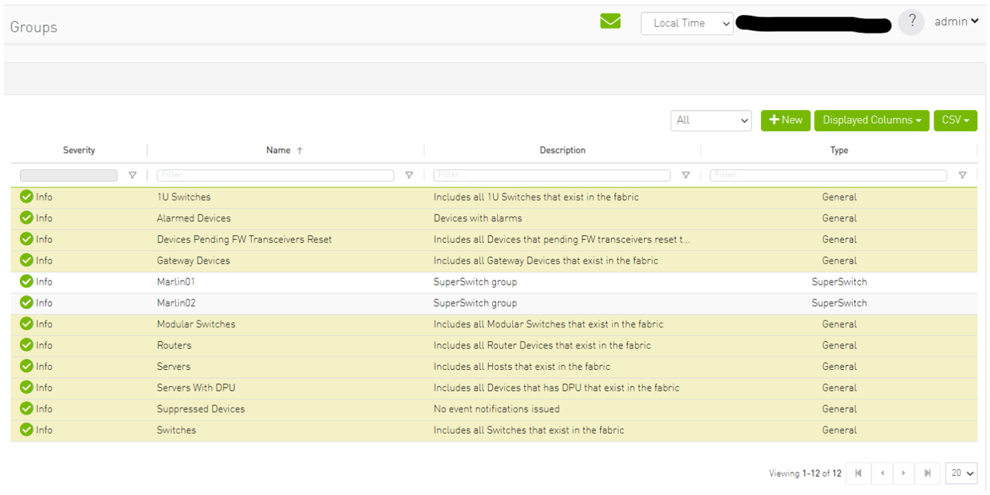
Upon selecting the group type SuperSwitch, additional columns containing information related to the SuperSwitch are added to the details view.
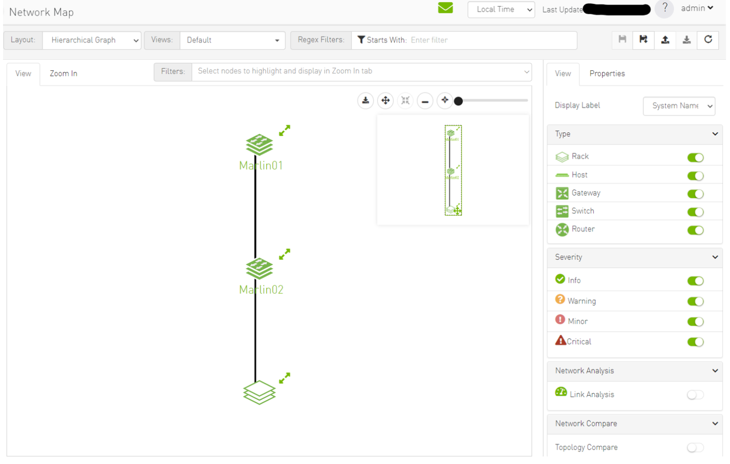
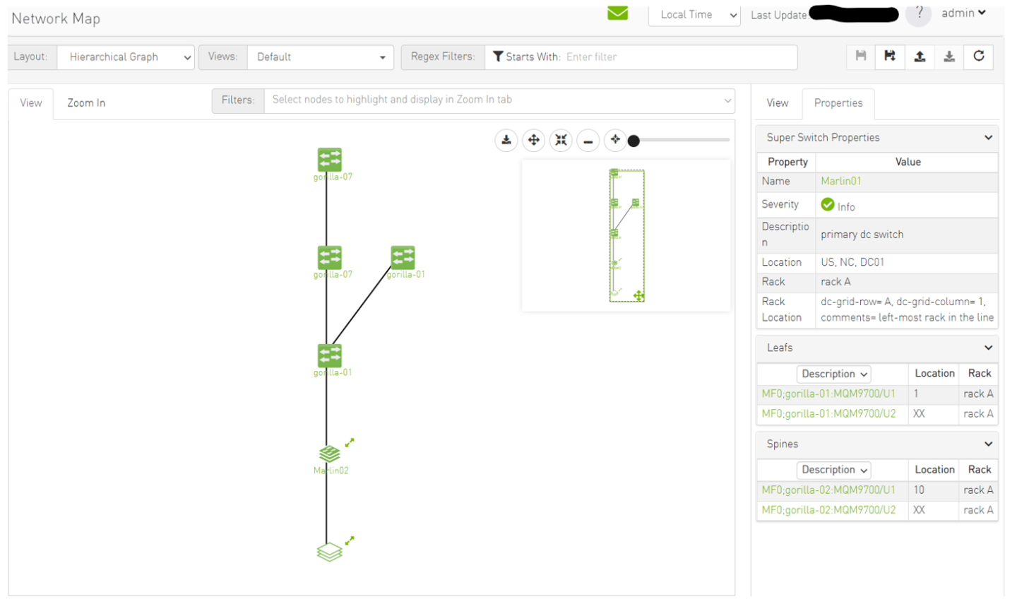
An icon for the SuperSwitch group in its collapsed view exists on the network map.
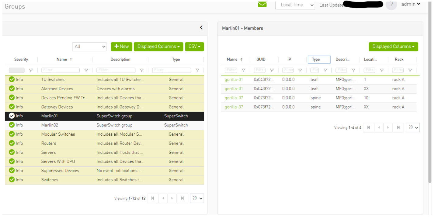
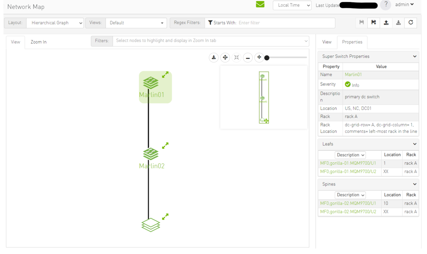
Upon selecting the SuperSwitch group, all of its properties can be viewed in the details view.
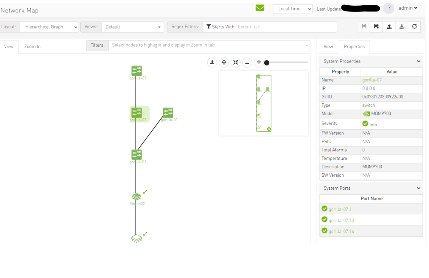
Expanding the SuperSwitch group icon displays all the switches included in the group as separate 1U switches, along with their respective properties.
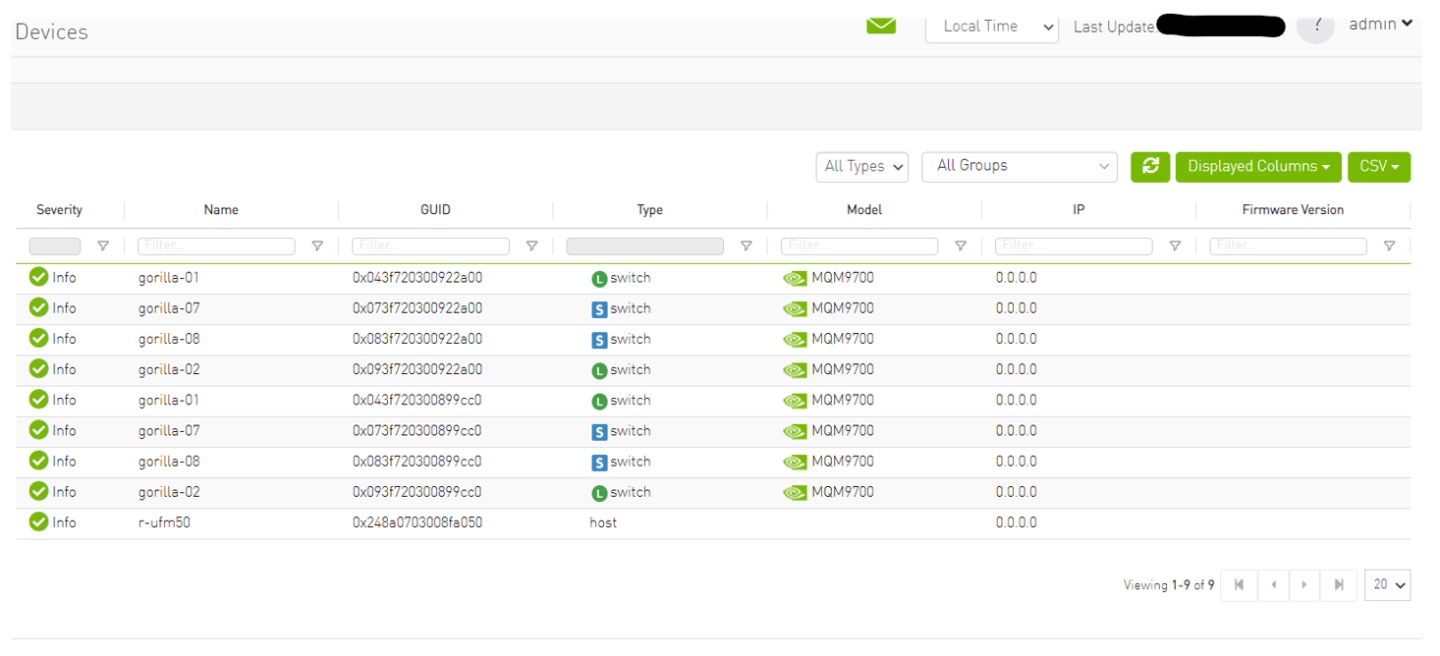
On the devices view, switches that are part of the SuperSwitch group are marked with an additional icon that indicates their role in the group. The "S" icon denotes spines, while the "L" icon denotes lines.
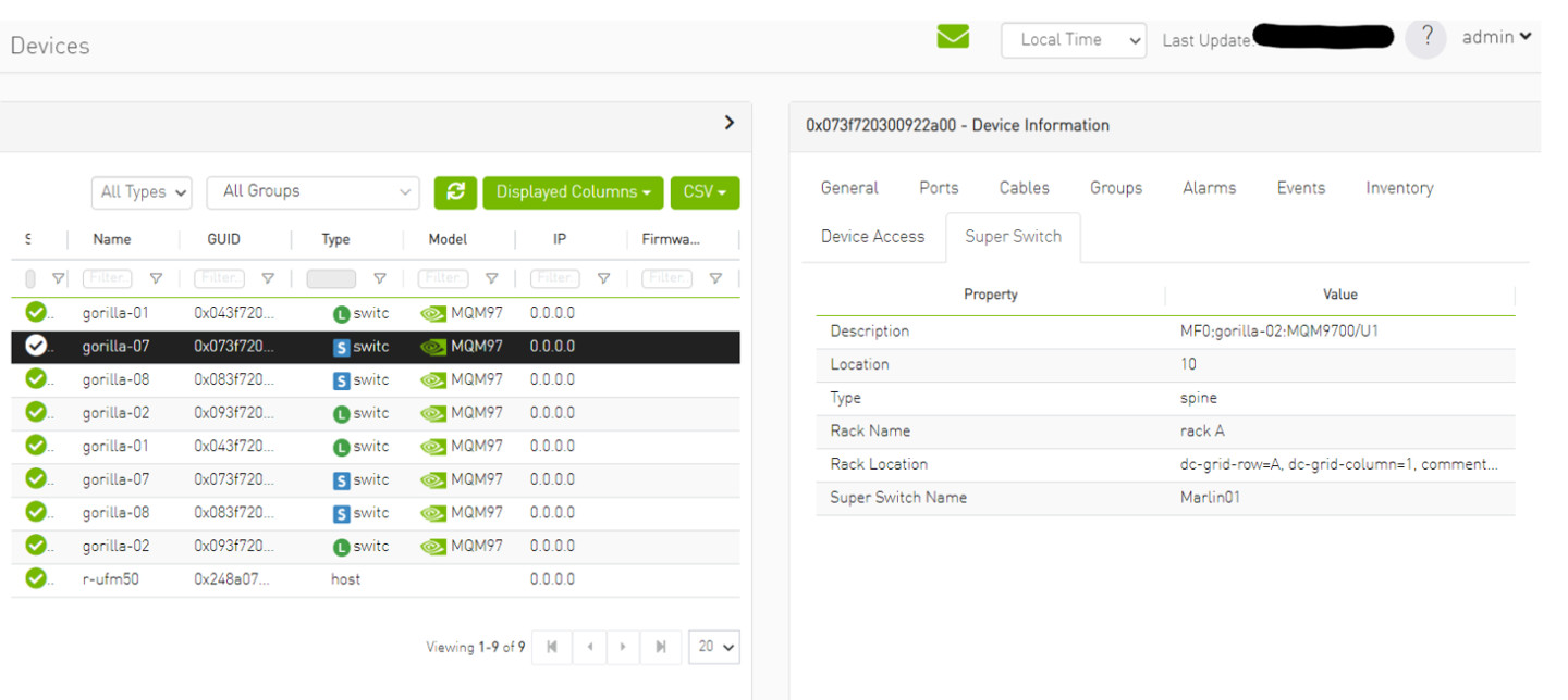
Selecting a switch that belongs to the SuperSwitch group in the properties view allows you to view all the switch properties related to the SuperSwitch group.
Each SuperSwitch definition can include one or more racks where each embedded rack can include multiple leafs and spines switches.