Chassis Power Up
Before initiating system power up, the cooling system must be deployed.
Before starting any procedure on the director switch system put an ESD prevention wrist strap on and connect to the chassis.
Before powering the CDU system, it is important to check the following:
The CDU is properly connected to the system
The main hose connector is not locked
All Spines and at least 1 Leaf is connected to the manifolds
The primary CDU loop is connected and the flow valves are open
Below is a step by step procedure for the cooling system power up.
Once the CDU boots up, there are two critical parameters that must be set up, the primary water loop temperature and the dew point.
Both are displayed on the CDU “Overview” screen. Make sure that the values displayed match the expected values by the DC design.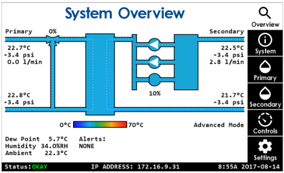
If the primary water loop temperature is within a few degrees range from the dew point temperature, the primary side hoses must be thermally isolated from the ambient air.
Calculate the desired secondary side temperature as follows:
Tsec=MIN[MAX(Tdew_point+15, Tprimary+10), 45C]
For example:T primary
T dew_point
T set_point
10
10
25
10
20
35
20
10
30
30
10
40
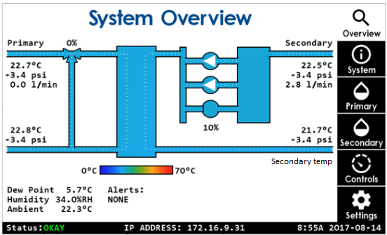
Go to “Controls” tab on CDU screen and select “Secondary temperature” mode, then use +/- on screen controls to set the desired temperature and press “Apply”.
Go to “Overview” screen and verify operating mode is updated to “Secondary temp”:
Refer to the “Expected Cooling System Performance” paragraph to verify the basic CDU functionality.
Before powering the AHX system, it is important to check the following:
The AHX system is properly connected to the switch system
The main hose connector is not locked
All Spines and at least 1 Leaf is connected to the manifolds
The primary AHX loop is connected and the flow valves are opened
During the start up phase, the AHX will boost all fan to 100%
Make sure to wear ear plugs or a protection headset
Below is a step by step procedure for the cooling system power up.
Once the AHX cooling system is plugged in, verify that the emergency EPO button is released and the unit should power itself up.
When the AHX system boots, an initial setup will be performed to match the performance of both system performance and the datacenter environment.
The parameters are: temperature, differential pressure set point, and pump operation mode. See below image of the Configuration Screen.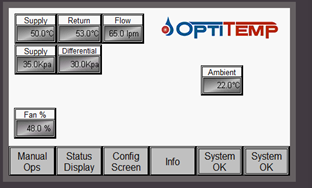 Warning
All the values are set to the tenth precision. To define the temperature to 23C for example, enter 230. Do not enter the period "." in the input.
Calculate the desired secondary side temperature as follows:
Tsec=MIN[Tamb+10, 35C]
After entering the temperature value, press the “Setpoint Temperature” button and update the values.
For example:T ambient
T set_point
10
20
20
30
25
35
30
35
Set the differential pressure to 50kPa
Select the “Setpoint Pressure” command, type 500 and press Enter.Set pump mode to “Differential pressure” mode.Select the “Pump Control” command, type “2” and press Enter:
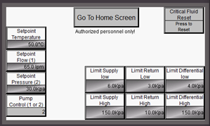
Select “Go To Home Screen”. It may take up to 3 minutes for the AHX system temperature to stabilize at the selected "set point".
Verify the pump speed, differential pressure and the fan speed. Fan speed may indicate 0% as there is no power load yet.
The System cannot be powered up without at least 1 management module attached to the chassis. Removing all Management modules will cause immediate system shutdown
It can take up to 5 minutes for the system to boot up. If any LED shows an amber color for more than 7 minutes turn off the system.
To power up the system, at least 1 management board should be fully inserted and latched within the chassis and all PSUs should be energized.
When the system boot up is completed you should observe the following:
PSU FRU: Status led green.
That the Status LED on each spine and leaf are green
MNG FRU: Status led, PSU Led, Fan Led - Green
Master LED should be green on one MNG module only. This is the Master MNG. The other MNG module if present should have its Master LED in OFF state.
IO panel leds should reflect those of MNG module/s.
LCD screen should show the login screen with the Mellanox logo.
The CS8500 switch system cannot be shut down remotely. To shutdown the switch system do one of the following:
Remove all management modules.
Cut the AC power for all PSUs.
To reboot any of the modules that are accessible through the CLI, use the command “reload” in “config” mode as shown in the following example:
switch (config)# reload