Switch IO Panel Interface
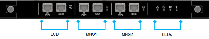
The system IO panel is divided into 4 sections (see below image and table):
LCD screen control
MNG1 interface
MNG2 interface
System status LEDs
Section | Symbol | Description |
LCD interface 
| 
| Std RJ45 1GB/100MB ETH connection to LCD tablet. Master MNG owns control over this port and controls functionality of LCD screen |

| RS232 console for LCD debug and configuration. Should be connected to the dedicated slot on LCD screen. | |
MNG 1 interface 
| 
| Std RJ45 1GB/100MB ETH connection to Management module #1 |

| I2C / RS232 console for system debug and configuration. Please use split cable provided with the system to get access to the relevant interface. | |
|
| MNG 1 Master / Slave led – refer to 3.1.6 for further information. | |
MNG 2 interface 
| 
| Std RJ45 1GB/100MB ETH connection to Management module #1 |

| I2C / RS232 console for system debug and configuration. Please use split cable provided with the system to get access to the relevant interface. | |
|
| MNG 2 Master / Slave led – refer to 3.1.6 for further information. | |
LEDs | See LEDs interface chapter for more information |