Hardware Installation
Installation and initialization of the BlueField BF1600 Controller Card require attention to the mechanical, power, and precautions for rack-mounted equipment.
Safety Warnings
Please observe all safety warnings to avoid injury and prevent damage to system components. Note that not all warnings are relevant to all models.
Note that not all warnings are relevant to all models.

| General Installation Instructions |

| Jewelry Removal Warning |
|
| Over-temperature |
|
| During Lightning - Electrical Hazard |
|
| Copper Cable Connecting/Disconnecting |
|
| Equipment Installation |
|
| Equipment Disposal |
|
| Local and National Electrical Codes |

| Hazardous Radiation Exposure
|
The installation procedure of BlueField Controller Card involves the following steps:
Step | Procedure | Direct Link |
1 | Unpack the package and confirm that you have received all the required components | Refer to “Package Contents” |
2 | Check the system’s hardware and software requirements. | Refer to System Requirements |
3 | Pay attention to the air flow consideration within the JBOF system | Refer to AirFlow Requirements |
4 | Follow the pre-installation check list | Refer to Pre-Installation Checklist |
5 | Install the BF1600 Controller Card in the JBOF system | Refer to “BF1600 Controller Card Installation Instructions - PCIe x16” |
Install the BF1600 Controller and Auxiliary Connection cards in the JBOF system | Refer to “BF1600 Controller and Auxiliary Connection Cards Installation Instructions” | |
7 | Configure the NVMe SSD devices in the JBOF system | Refer to the devices’ documentation for any pre-installation configuration requirements. |
8 | Connect the ATX power supply to the BF1600 Controller Card | |
9 | Power on the system | |
10 | Perform initial system bring-up | |
Hardware Requirements
Unless otherwise specified, NVIDIA products are designed to work in an environmentally controlled data center with low levels of gaseous and dust (particulate) contamination.
The operating environment should meet severity level G1 as per ISA 71.04 for gaseous contamination and ISO 14644-1 class 8 for cleanliness level.
Airflow Requirements
BlueField 1600 Controller Card is offered with one airflow pattern: from the BlueField SoC to the QSFP28 ports.

All systems in the same rack should be planned with the same airflow direction. All components need to have the same airflow direction.
Please refer to the Specifications section for airflow numbers for each specific card model.
Software Requirements
See Operating Systems/Distributions section under the Introduction section.
Software Stacks - The BF1600 Controller Card is shipped with Linux based Operating System burned on it which includes all needed drivers. For more information, please refer to the BlueField Software User Manual.
1. Unpack the BF1600 Controller Card
Unpack and remove the BF1600 Controller Card. Check against the package contents list that all the parts have been sent. Check the parts for visible damage that may have occurred during shipping. Please note that the cards must be placed on an antistatic surface. For package contents please refer to Package Contents.
Please note that if the card is removed hastily from the antistatic bag, the plastic ziplock may harm the EMI fingers on the QSFP connector. Carefully remove the card from the antistatic bag to avoid damaging the EMI fingers.
1. Turn off the power to the JBOF system.
Turn off the power to the JBOF system, and disconnect the power cord and remove the cover. Refer to the JBOF system documentation for instructions. Before you install the BF1600 Controller card, make sure that the system is disconnected from power and any networks.
2. (Optional) Check the mounting bracket on the PCIe Auxiliary Connection Card.
If required for your JBOF system, replace the full-height mounting bracket that is shipped mounted on the PCIe Auxiliary Card with the supplied low-profile bracket. Refer to Bracket Replacement Instructions.
The BF1600 Controller Card and auxiliary connection card are shipped with assembled high-profile brackets. If this form factor is suitable for your requirements, you can skip the remainder of this section and move to Installation Instructions. If you need to replace the Auxiliary Connection Card with the short bracket that is included in the shipping box, please follow the instructions in this section.
Due to risk of damaging the EMI gasket, it is not recommended to replace the bracket more than three times.
To replace the brackets you will need the following parts:
The new bracket of the proper height
The 2 screws saved from the removal of the brackets
Removing the Existing Bracket
Using a torque driver, remove the two screws holding the bracket in place.
Separate the bracket from the Auxiliary Connection card.
Save the two screws.
Installing the New Bracket
Place the bracket onto the card until the screw holes line up.
Screw on the bracket using the screws saved from the bracket removal procedure above.
WarningUse a torque driver to apply up to 4.4 lbs-in torque on the screws.
This section provides detailed instructions on how to install your BlueField 1600 Controller Card in a JBOF system.
The BlueField BF1600 Controller Card should be installed only in a JBOF System as it functions as a PCIe root-complex (RC) initiating PCIe bus operations. Installing it in a regular host system may damage the card.
Please note that the following figures are for illustration purposes only.
See below direct links to the installation instructions depending on the part number you have purchased.
Form Factor | Direct Link to Installation Instructions |
PCIe x16 BF1600 Controller Cards: | “BF1600 Controller Card Installation Instructions - PCIe x16” |
2x PCIe x16 BF1600 Controller Cards: | “BF1600 Controller and Auxiliary Connection Cards Installation Instructions” |
BF1600 Controller Card Installation Instructions - PCIe x16
Applies to MBF1M606A-CSNAT, MBF1M616A-CSNAT and MBF1M646A-CSNAT.
Connect the BF1600 Controller Card in an available PCI Express slot on the JBOF system.
Step 1. Locate an available PCI Express x16 slot.
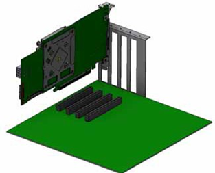
Step 2. Applying even pressure at both corners of the card, insert the BF1600 Controller Card in a PCI Express slot until firmly seated.
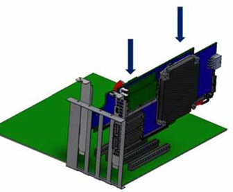
Do not use excessive force when seating the card, as this may damage the system or the auxiliary PCIe connection card.
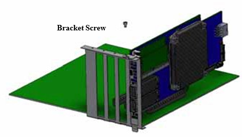
Secure the BF1600 Controller Card to the JBOF system.
Step 1. Secure the bracket to the JBOF system with the bracket screw.
BF1600 Controller and Auxiliary Connection Cards Installation Instructions - PCIe x32
Applies to MBF1M626A-CSNAT, MBF1M636A-CSNAT and MBF1M656A-CSNAT.
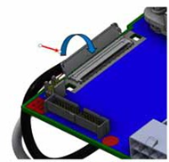
Connect the BF1600 Controller Card with the Auxiliary connection card using the supplied CABLINE-CAII PLUS harnesses.
Step 1. Plug the CABLINE-CAII PLUS harness on the BF1600 Controller Card while paying attention to the color-coding. As indicated on both sides of the card; plug the black harness to the component side and the white harness to the print side.
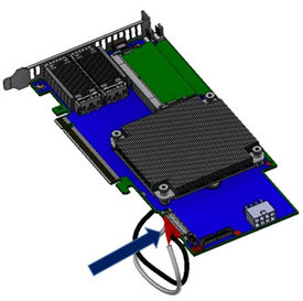
Step 2. Verify the plugs are locked.
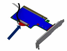
Step 3. Plug the CABLINE-CAII PLUS harness on the PCIe Auxiliary Card. As indicated on both sides of the Auxiliary connection card; plug the black harness to the component side and the white harness to the print side.
Connect the BF1600 Controller Card in an available PCI Express slot on the JBOF system.
Step 1. Locate an available PCI Express x16 slot.
Step 2. Applying even pressure at both corners of the card, insert the BF1600 Controller Card in a PCI Express slot until firmly seated.
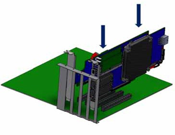
Do not use excessive force when seating the card, as this may damage the system or the auxiliary PCIe connection card.
Connect the PCIe Auxiliary Connection Card in an available PCI Express slot on the JBOF system.
Step 1. Locate an available PCI Express x16 slot.
Step 2. Applying even pressure at both corners of the card, insert the card in a PCI Express slot until firmly seated.
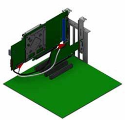
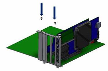
Secure the BF1600 Controller and PCIe Auxiliary Connection Cards to the JBOF system.
Step 1. Secure the bracket to the JBOF system with the bracket screw.
Do not use excessive force when seating the card, as this may damage the system or the adapter.
Networking Cables
All networking cables can be inserted or removed with the unit powered on.
To insert a cable, press the connector into the port receptacle until the connector is firmly seated.
Support the weight of the cable before connecting the cable to the adapter card. Do this by using a cable holder or tying the cable to the rack.
Determine the correct orientation of the connector to the card before inserting the connector. Do not try and insert the connector upside down. This may damage the adapter card.
Insert the connector into the adapter card. Be careful to insert the connector straight into the cage. Do not apply any torque, up or down, to the connector cage in the adapter card.
Verify that the connector locks in place.
WarningWhen installing cables make sure that the latches engage.
ImportantAlways install and remove cables by pushing or pulling the cable and connector in a straight line with the card.
After inserting a cable into a port, the Amber LED indicator will light when the physical connection is established (that is, when the unit is powered on and a cable is plugged into the port with the other end of the connector plugged into a functioning port).
After plugging in a cable, lock the connector using the latching mechanism particular to the cable vendor. When data is being transferred the Green LED will blink. See Networking LED Interfaces.
Care should be taken as not to impede the air exhaust flow through the ventilation holes. Use cable lengths that allow for routing horizontally around to the side of the chassis before bending upward or downward in the rack.
To remove a cable, disengage the locks and slowly pull the connector away from the port receptacle. The LED indicator will turn off when the cable is unseated.