OSPF
Open Shortest Path First (OSPF) is a link-state routing protocol for IP networks. It uses a link state routing algorithm and falls into the group of interior routing protocols, operating within a single autonomous system (AS).
OSPF-speaking routers send Hello packets on all OSPF-enabled IP interfaces. If two routers sharing a common data link agree on certain parameters specified in their respective Hello packets, they become neighbors.
Adjacencies, which can be thought of as virtual point-to-point links, are formed between some neighbors. OSPF defines several network types and several router types. The establishment of an adjacency is determined by the types of routers exchanging Hellos and the type of network over which the Hello packets are exchanged.
Each router sends link-state advertisements (LSAs) over all adjacencies. The LSAs describe all of the router’s links, or interfaces, the router's neighbors, and the state of the links. These links might be to stub networks (those without another router attached), to other OSPF routers, to networks in other areas, or to external networks (those learned from another routing process). Because of the varying types of link-state information, OSPF defines multiple LSA types.
Each router receiving an LSA from a neighbor records the LSA in its link-state database and sends a copy of the LSA to all of its other neighbors. By flooding LSAs throughout an area, all routers will build identical link-state databases.
When the databases are complete, each router uses the SPF algorithm to calculate a loop-free graph describing the shortest (lowest cost) path to every known destination, with itself as the root.
When all link-state information has been flooded to all routers in an area, and neighbors have verified that their databases are identical, it means the link-state databases have been synchronized and the route tables have been built. Hello packets are exchanged between neighbors as keepalives, and LSAs are retransmitted. If the network topology is stable, no other activity should occur.For OSPF network design over NVIDIA L3 VMS, please refer to the Virtual Modular Switch Reference Guide.
The router ID is a 32-bit number assigned to the router running the OSPF protocol. This number uniquely identifies the router in the OSPF link-state database.
Router ID can be configured statically, however, if it is not configured, then the default election is as follows:
If a loopback interface already exists, the router ID selects the highest loopback IP address assigned to a loopback interface. Effective tunnel IP is considered as loopback address.
Otherwise, the the highest IP address assigned to any other interface on the system is selected as router ID.
Equal-cost multi-path (ECMP) routing is a routing strategy where next-hop packet forwarding to a single destination can occur over multiple paths. The OSPF link-state routing algorithm can find multiple routes to the same destination, all multiple routes are added to the routing table only if those routes are equal-cost routes.
In case there are several routes with different costs, only the route with the lowest cost is selected. In case there are multiple routes with the same lowest cost, all of them are used (up to maximum of 64 ECMP routes).
ECMP is not configurable but is enabled by default for OSPF.

Prerequisites:
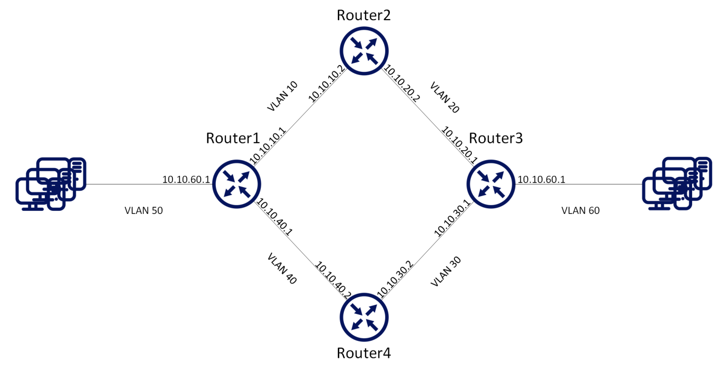
The following configuration example refers to Router 2 in the figure above The remainder of the routers in the figure are configured similarly.
It is recommended to disable STP before enabling OSPF. Use the command “no spanning-tree”.
Enable IP routing functionality. Run:
switch(config)# ip routingEnable the desired VLAN. Run:
switch(config)# vlan10switch(config)# vlan20Add this VLAN to the desired interface. Run:
switch(config)#interfaceethernet1/1switch(config ethernet1/1)# switchport access vlan10switch(config ethernet1/1)# exitswitch(config)#interfaceethernet1/2switch(config ethernet1/2)# switchport access vlan20Create a VLAN interface. Run:
switch(config)#interfacevlan10Apply IP address to the VLAN interface. Run:
switch(configinterfacevlan10)# ip address10.10.10.2/16Enable the interface. Run:
switch(configinterfacevlan10)# no shutdownCreate a second VLAN interface. Run:
switch(config)#interfacevlan20Apply IP address to the second VLAN interface. Run:
switch(configinterfacevlan20)# ip address10.10.20.2/16Enable the second interface. Run:
switch(configinterfacevlan20)# no shutdown
Basic OSPF Configuration:
Enable OSPF configuration commands. Run:
switch(config)# protocol ospfCreate an OSPF instance. Run:
switch(config)# router ospfWarningOnly one instance of OSPF per VRF is supported.
Associate the VLAN interfaces to the OSPF area. Area 0 is the backbone area. Run:
switch(configinterfacevlan10)# ip ospf area0switch(configinterfacevlan10)# exitswitch(config)#interfacevlan20switch(configinterfacevlan20)# ip ospf area0
To verify OSPF configuration and status:
Verify OSPF configuration and status. Run:
switch(config) # show ip ospf Routing Process1with ID10.10.10.10vrf-defaultStateful High Availability disabled Graceful-restart is not supported Supports only single TOS (TOS0) route Opaque LSA not supported OSPF Admin State is enabled Redistributing External Routes: Disabled Administrative distance110Reference Bandwidth is 100Gb Initial SPF schedule delay1msecs SPF Hold time10msecs Maximum paths to destination64Router is not originating router LSA with maximum metric Condition: Always Number of external LSAs0, checksum sum0Number of opaque AS LSAs0,checksum sum0Number of areas is1,1normal,0stub,0nssa Number of active areas is1,1normal,0stub,0nssa Area (0.0.0.0) (Active) Interfaces inthisarea:2Active Interfaces:2Passive Interfaces:0SPF Calculation has run5times This area is Normal area Number of LSAs:1, checksum sum7700Verify the OSPF neighbors status. Make sure that each neighbor reaches FULL state with its peer to enable it take part in all dynamic routing changes in the network. Run:
switch(config) # show ip ospf neighbors Neighbor10.10.10.1,interfaceaddress10.10.10.2In the area0.0.0.0viainterfaceVlan10Neighbor priority is1, State is FULL BDR is10.10.10.1Options0Dead timer due in35Neighbor10.10.20.1,interfaceaddress10.10.20.2In the area0.0.0.0viainterfaceVlan20Neighbor priority is1, State is FULL BDR is10.10.20.1Options0Dead timer due in35Verify the OSPF interface configuration and status. Run:
switch(config) # show ip ospfinterfaceInterface Vlan is10Enabled, line protocol is Down IP address10.10.10.2, Mask255.255.0.0[primary] Process ID1VRF Default, Area0.0.0.0OSPF Interface Admin State is enabled State DOWN, Network Type BROADCAST, Cost1Transmit delay1sec, Router Priority1No designated router onthisnetwork No backup designated router onthisnetwork Timer intervals (sec's): Hello10, Dead40, Wait40, Retransmit5No authentication Number of opaque link LSAs:0, checksum sum0Interface Vlan is20Enabled, line protocol is Up IP address10.10.20.2, Mask255.255.0.0[primary] Process ID1VRF Default, Area0.0.0.0OSPF Interface Admin State is enabled State DESIGNATED ROUTER, Network Type BROADCAST, Cost1Transmit delay1sec, Router Priority1No designated router onthisnetwork No backup designated router onthisnetwork Timer intervals (sec's): Hello10, Dead40, Wait40, Retransmit5No authentication Number of opaque link LSAs:0, checksum sum0
For more information about this feature and its potential applications, please refer to the following community post: