Cable Installation
In some switch models, the product's package includes cable retainers. It is highly recommended to use them in order to secure the power cables in place. Please adhere to the following instructions:
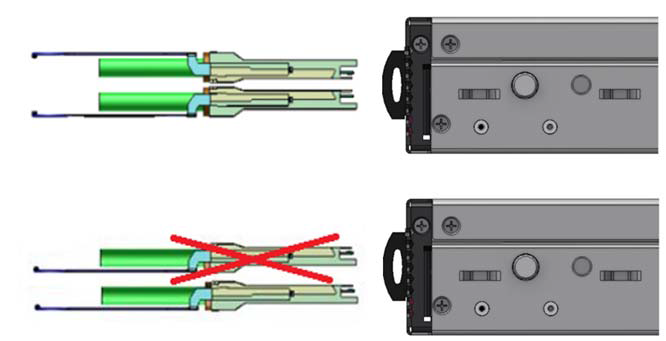
Verify the integrity of the retainer assembly, as demonstrated in the below table:- The snaps' push-pins must have visible edges with no broken or torn parts.
- The shoulders' pins should be in-tact and must not be bent inwards.
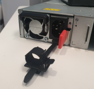
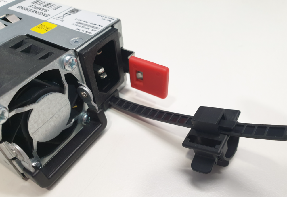
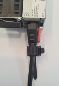
It is advised to place the PSU on a flat, stable surface. While you secure the PSU in place, use two thumbs to insert the retainer's two snaps into the designated holes located near the AC inlet. Make sure that the retainer's plastic loop is facing upwards, as demonstrated in the below table.
NoteFor demonstration purposes, the images in this document show C2P (Connector-to-Power) airflow PSUs with red latches, yet the instructions apply to P2C (Power-to-Connector) PSUs with blue latches as well.
Correct Insertion
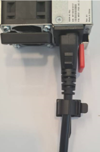
Incorrect Insertion
Push the retainer until the shoulders' pins are open and aligned with the PSU front panel, as shown in the following table:
Make sure that the retainer is fully locked in place by gently attempting to pull it outwards.
Open the plastic loop and route the AC cord through it. Locate the loop over the AC cord, as shown in the following table, and fasten it tightly.
Proper Loop Placement
Improper Loop Placement
Each cable retainer can be used once only. Once the retainer has been fully inserted and the shoulders' pins have been adjusted, the retainer cannot be used again, and should be discarded if pulled out.
All cables can be inserted or removed with the unit powered on.
To insert a cable, press the connector into the port receptacle until the connector is firmly seated. The LED indicator, corresponding to each data port, will light when the physical connection is established. When a logical connection is made, the relevant port LED will turn on.
To remove a cable, disengage the locks and slowly pull the connector away from the port receptacle. The LED indicator for that port will turn off when the cable is unseated.
For a list of Supported Cables and Transceivers, please refer to LinkX interconnect guides.
For full cabling guidelines, please refer to NVIDIA Cable Management Guidelines and FAQs Application Note.
For more information about port LEDs, refer to Port LEDs.
Do not force the cable into the cage with more than 40 newtons/9.0 pounds/4kg force. Greater insertion force may cause damage to the cable or to the cage.
QSFP Cable Orientation
Splitter (Breakout) Cables and Adapters
A 100GbE port can be split to two 50GbE ports, or to four (or less) 25GbE ports, using an NVIDIA splitter cable.
Splitting a 100GbE QSFP28 port to 4 separate 25GbE ports (using a splitter cable) may disable (unmap) the 100GbE port below it. See specific splitting options per system detailed below.
SN2201/SN2201_M Splitting Options
All QSFP28 ports are splittable. Each port can be split into 4xSFP28 (10/25G) or 2xQSFP28 (50G) ports. There are no blocking requirements.