SN3510 Fixed Rail Kit
This document is preliminary and subject to change.
|
Kit OPN |
Rack Size and Rack Depth Range |
|
MTEF-KIT-C |
430-800 mm |
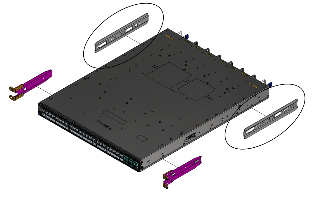
The following parts are included in the fixed rail kit (see figure below):
- 2x Rack mount rails (A)
- 2x Rack mount blades (B)
- 2x Rack mount ears (C)
- 8x M6 Standard cage nuts (D)
- 8x M6 Standard pan-head Phillips screws (E)
- 4x Flat Head Phillips 100 DEG 6-32X1/4" ST.ST PATCH 360 (F)
| Rack Rail Kit Parts |

|
Prerequisites:
Before mounting the system to the rack, select the way you wish to place the system. Pay attention to the airflow within the rack cooling, connector and cabling options.
While planning how to place the system, consider the two installation options shown in the figures below, and review the following points:
- Make sure the system air flow is compatible with your installation selection. It is important to keep the airflow within the rack in the same direction.
- Note that the part of the system to which you choose to attach the rails (the front panel direction, as demonstrated in Option 1 or the FRUs direction, as demonstrated in Option 2) will determine the system’s adjustable side. The system’s part to which the brackets are attached will be adjacent to the cabinet.
- The FRU side is extractable. Mounting the rack brackets inverted to the FRU side (Option 2) will allow you to slide the FRUs, in and out.
Short Racks (430-580 mm) Installation Options
|
Front Side (Ports) |
Rear Side (FRUs) |
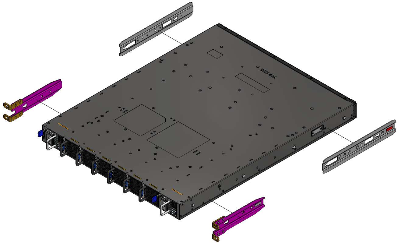
|
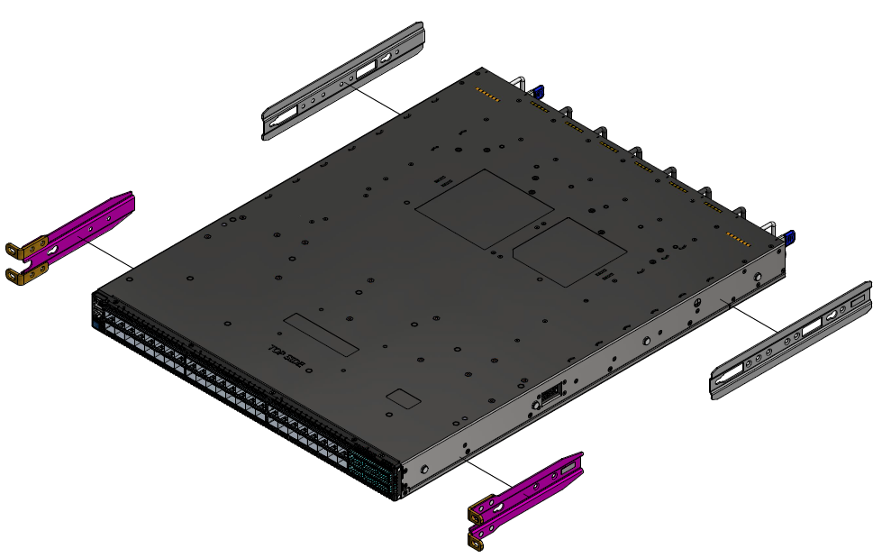
|
Standard Racks (580-800 mm) Installation Options
|
Front Side (Ports) |
Rear Side (FRUs) |
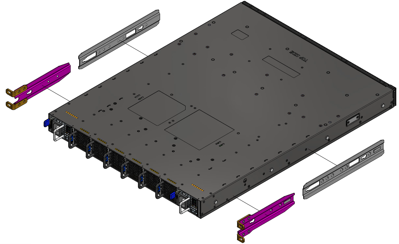
|
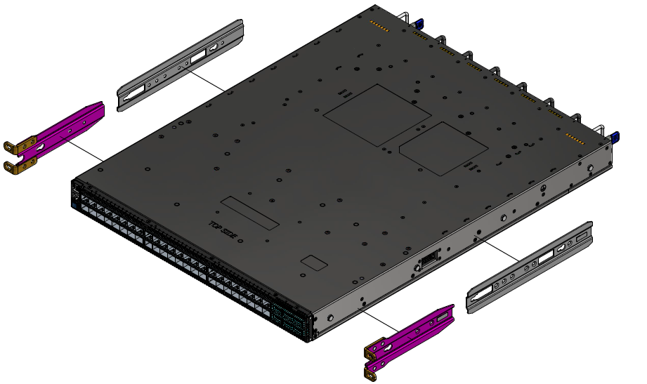
|
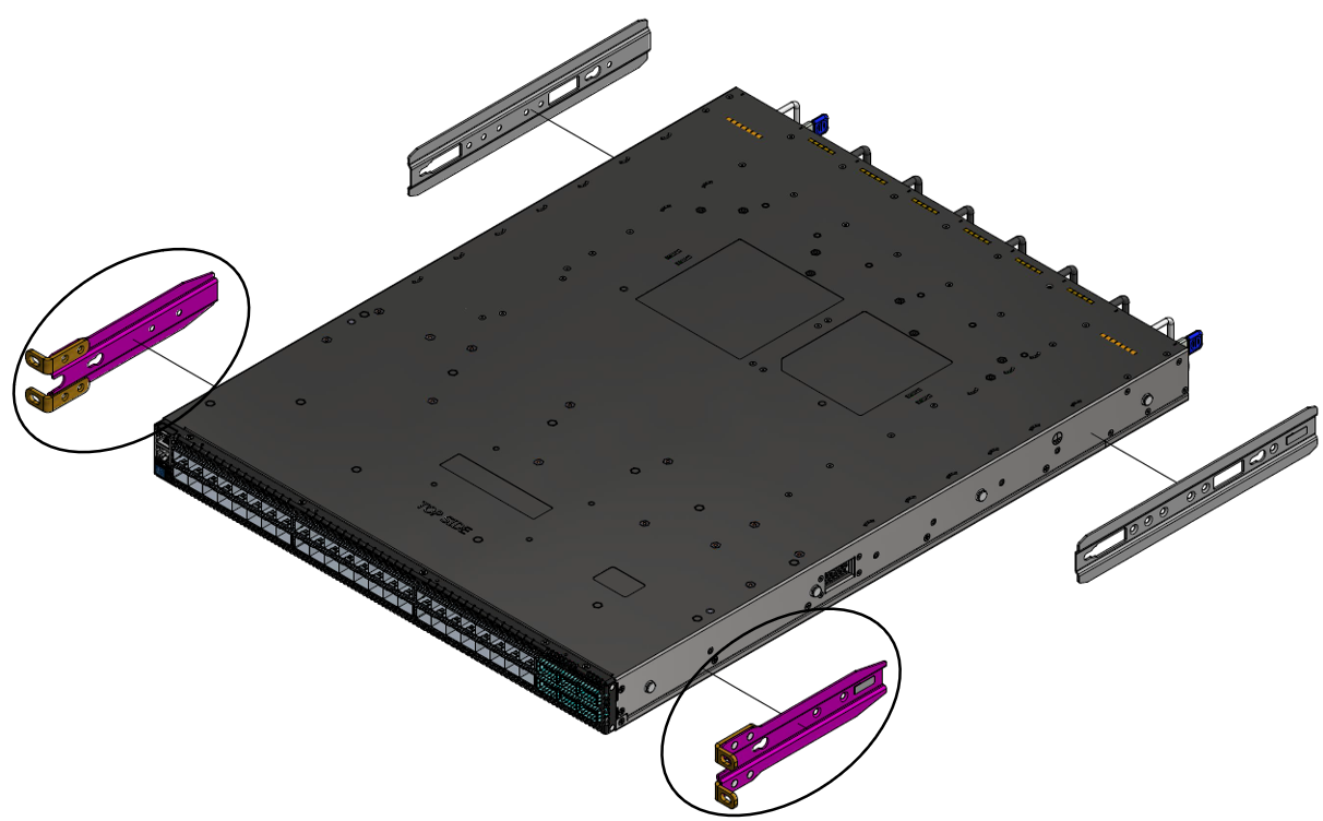
To mount the system into the rack:
The following steps include illustrations that show front side (ports) installation, yet all instructions apply to all installation options.
- Attach the left and right rack mount rails (A) to the switch, by gently pushing the switch chassis’ pins through the slider key holes, until locking occurs.
Secure the chassis in the rails by screwing 2 flat head Phillips screws (F) in the designated points with a torque of 1.5±0.2 Nm.
Attaching the Rails to the Chassis
Attach the left and right rack mount ears (C) to the switch, by gently pushing the switch chassis’ pins through the slider key holes, until locking occurs. Secure the system in the brackets by screwing the remaining 2 flat head Phillips screws (F) in the designated points with a torque of 1.5±0.2 Nm.
Attaching the Brackets to the Chassis
Install 8 cage nuts (D) in the desired 1U slots of the rack: 4 cage nuts in the non-extractable side and 4 cage nuts in the extractable side.
Installing the Cage Nuts
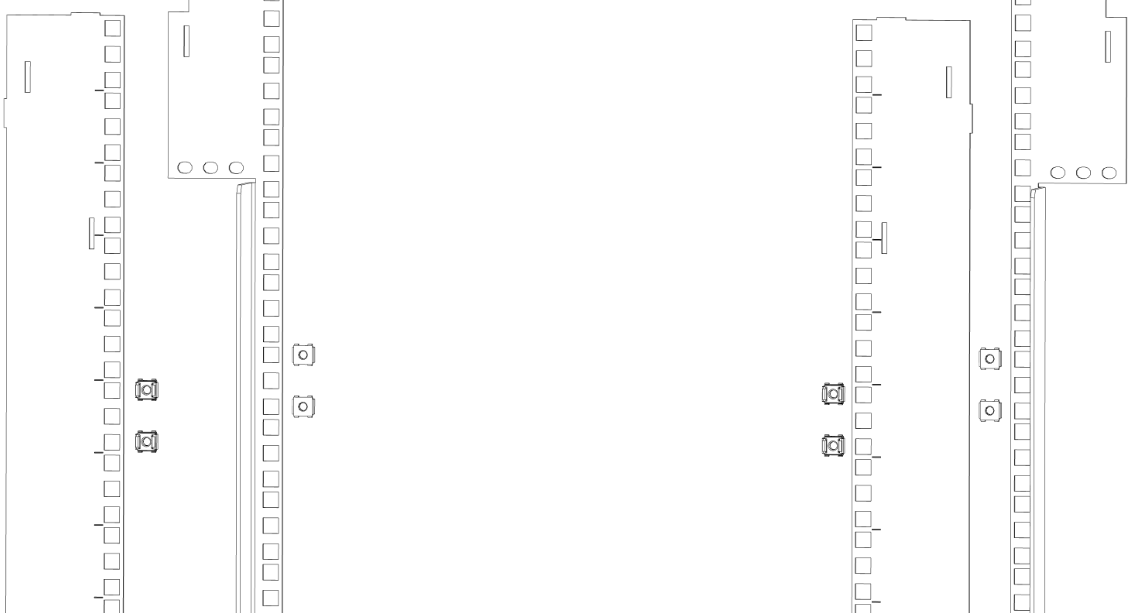 Note
NoteWhile each rack U (unit) consists of three holes, the cage nut should be installed vertically with its ears engaging the top and bottom holes only.
While your installation partner is supporting the system’s weight, perform the following steps:
Attach the two rack mount blades (B) to the back side (FRU side) of the rack by inserting four M6 screws (E) in the designated cage nuts. Do not tighten the screws yet.
Attaching the Brackets to the Rack
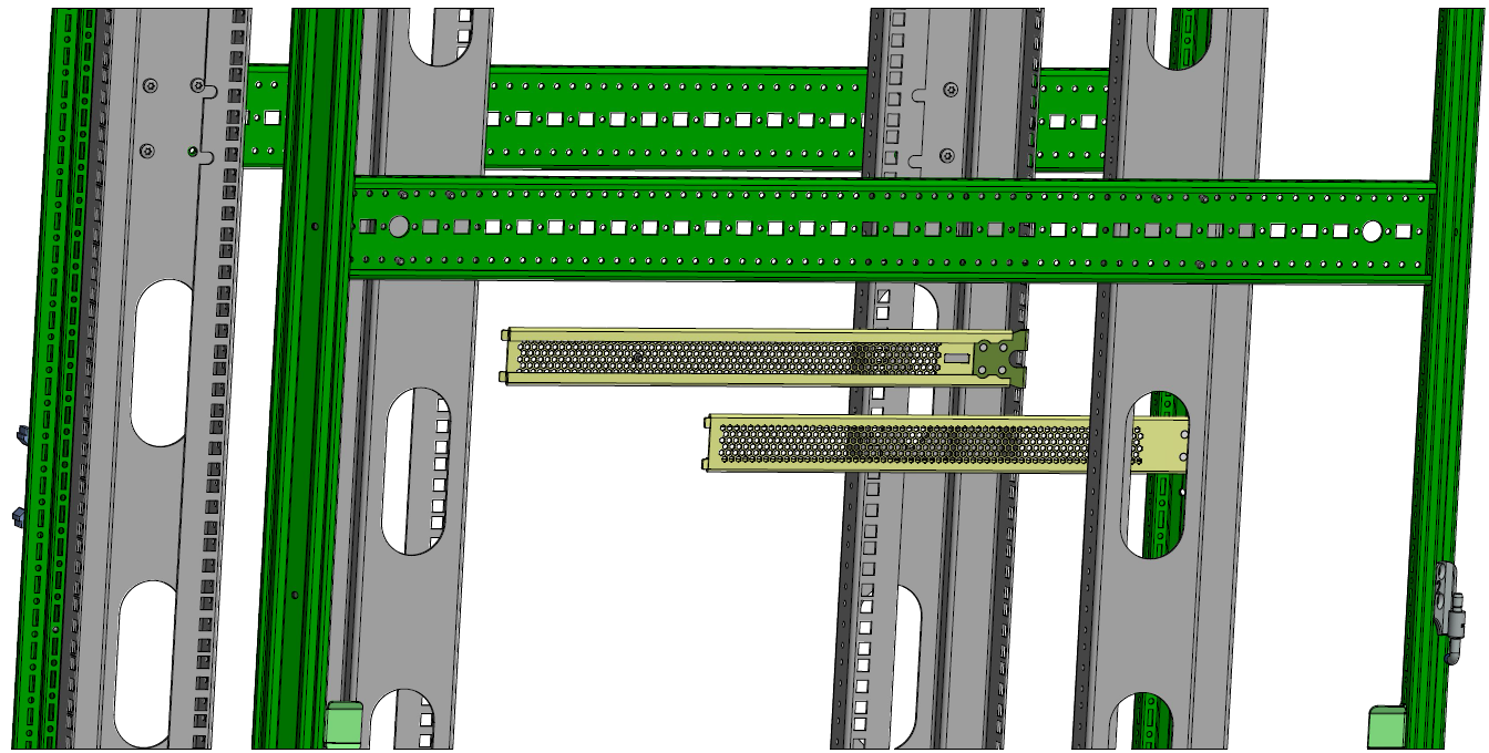
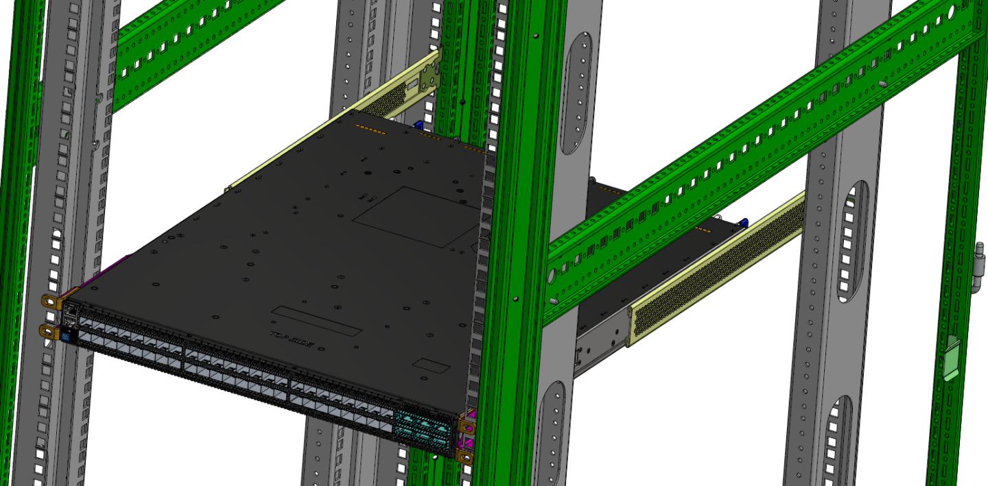
Slide the switch with the rails (A) and ears (C) installed on it into the left and right rails (B) on the rack. Use four M6 screws (E) to fix the rack mount ears (C) to the rack. Do not tighten the screws yet.
Sliding the Blades in the Rails
 Warning
At least two people are required to safely mount the system in the rack.
- When fully inserted, fix the switch by tightening the 8 screws (E) inserted in Step 5 and Step 6 with a torque of 4.5±0.5.
To remove a unit from the rack:
Turn off the system and disconnect it from peripherals and from the electrical outlet.
While your installation partner is supporting the system’s weight:
Loosen the screws attaching the rack mount ears (C) to the rack. Do not remove them yet.
Loosen the screws attaching the rack mount blades (B) to the rack, and pull the blades towards you, while your partner is holding the system.
Extract the loosened screws from Step 2 and dismount the system from the rack.
Remove the rails and brackets from the chassis by unscrewing 4 screws.