Introduction to the NVIDIA DGX-1 Deep Learning System
The NVIDIA® DGX-1™ Deep Learning System is the world’s first purpose-built system for deep learning with fully
integrated hardware and software that can be deployed quickly and easily.

Using the DGX-1: Overview
The NVIDIA DGX-1 comes with a base operating system consisting of an Ubuntu OS, Docker, Docker Engine Utility for NVIDIA GPUs, and NVIDIA drivers. Ths system is designed to run a number of NVIDIA-optimized deep learning framework applications packaged in Docker containers. You can use your own scheduling and management software to run jobs, and also build and run your own applications on the DGX-1.
Hardware Specifications
Components
| Component | Qty | Description |
|---|---|---|
| Base Server | 1 | Dual Intel® Xeon® CPU motherboard with x2 9.6 GT/s QPI, 8 Channel with 2 DPC DDR4, Intel®C610 Chipset, AST2400 BMC |
| 1 | GPU Baseboard supporting 8 SXM2 modules (Cube Mesh) and 4 PCIE x16 slots for InfiniBand/Ethernet NICs | |
| 1 | Chassis with 3+1 1600W Power supply and support for up to five 2.5 inch drives | |
| 1 | 10/100BASE-T IPMI Port | |
| 1 | RS232 Serial Port | |
| 2 | USB 3.0 Ports (set as USB 2.0 by default. To enable USB 3.0, see Enabling USB 3.0 for instructions.) | |
| Power Supply | 4 | 1600 W each. |
| CPU | 2 | Intel® Xeon® E5-2698 v4, 20-core, 2.2GHz, 135W |
| GPU | 8 | (Pascal) Tesla P100, featuring
|
| System Memory | 16 | 32 GB DDR4 LRDIMM (512 GB total) |
| SAS Raid Controller | 1 | 8 port LSI SAS 3108 RAID Mezzanine |
| Storage (RAID 0) (Data) | 4 | 1.92 TB, 6 Gb/s, SATA 3.0 SSD |
| Storage (OS) | 1 | 480 GB, 6 Gb/s, SATA 3.0 SSD |
| 10 GbE NIC | 1 | Dual port, 10GBASE-T, network adapter Mezzanine |
| InfiniBand EDR/100GbE NIC | 4 | Single port, x16 PCIe, Mellanox ConnectX-4 VPI MCX455A-ECAT
or Single port, x16 PCIe, Mellanox ConnectX-5 VPI MCX555A-ECAT |
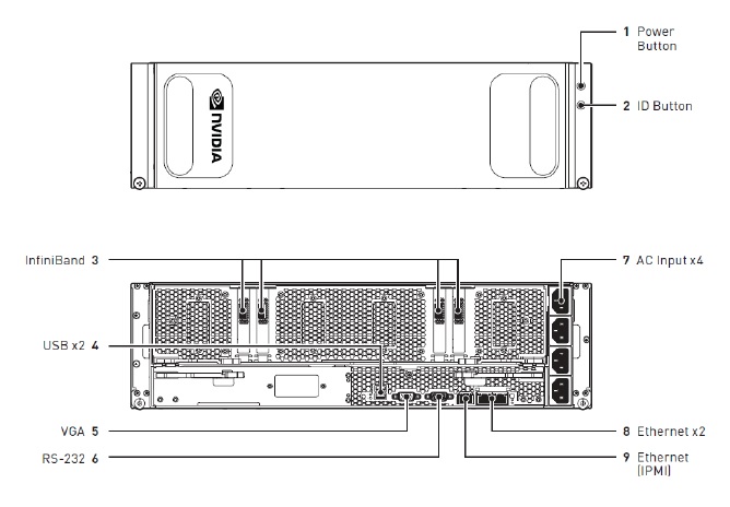
Connections and Controls
| ID | Type | Qty | Description |
|---|---|---|---|
| 1 | Power button | 1 |
Press to turn the DGX-1 on or off. Blue: System power on Off: System power off Amber (blinking): DC power Off, fault reported in BMC SEL Amber and blue (blinking): DC power On and fault reported in BMC SEL |
| 2 | ID button | 1 | Press to cause an LED on the back of the unit to flash as an identifier during servicing. |
| 3 | InfiniBand/Ethernet (QSFP28) | 4 | EDR IB/100GbE |
| 4 | USB | 2 | USB 3.0 ports are available to connect a keyboard. |
| 5 | VGA | 1 | The VGA port connects to a VGA capable monitor for local viewing of the DGX-1 setup console or base OS. |
| 6 | DB9 | 1 | RS232 serial port for internal debugging |
| 7 | AC input | 4 | Power supply inputs |
| 8 | Ethernet (RJ45) | 2 | 10GBASE-T dual port network adapter Mezzanine |
| 9 |
IPMI (RJ45) |
1 | 10/100BASE-T Intelligent Platform Management Interface (IPMI) port |
Rear Panel Power Controls

| ID | Type | Qty | Description |
|---|---|---|---|
| 1 | Power button | 1 |
Press and immediately release the power button for a graceful shutdown of the host OS. Press and hold the power button for at least four seconds to shut down the system immediately. The BMC remains live. |
| 2 | Power LED | 1 |
Off: Power off Blue (steady): Power on Blue (blinking): BMC reports system health fault. |
| 3 | Main Board Status LED | 1 |
Off: Normal Amber (blinking): BMC reports system health fault. |
LAN LEDs
LEDs next to each Ethernet port indicate the connection status as described in the table below:

| LED | Status | Description |
|---|---|---|
|
1 (Port 1 Link/Activity) |
Amber (steady) | LAN link |
| Amber (blinking) | LAN access (off when there is traffic) | |
| Off | Disconnected | |
|
2 (Port 1 Speed) |
Green | 10 Gb/s |
| Amber | 1 Gb/s | |
| Off | 100 Mb/s | |
|
3 (Port 0 Link/Activity) |
Amber (steady) | LAN link |
| Amber (blinking) | LAN access (off when there is traffic) | |
| Off | Disconnected | |
|
4 (Port 0 Speed) |
Green | 10 Gb/s |
| Amber | 1 Gb/s | |
| Off | 100 Mb/s |

Hard Disk Indicators

 HDD present
LED
HDD present
LED
 HDD activity
LED
HDD activity
LED
