Maintaining and Servicing the NVIDIA DGX-1
Be sure to familiarize yourself with the NVIDIA Terms & Conditions documents before attempting to perform any modification or repair to the DGX-1. These Terms & Conditions for the DGX-1 can be found through the NVIDIA DGX Systems Support page.
Problem Resolution and Customer Care
Log on to the NVIDIA Enterprise Support site for assistance with troubleshooting, diagnostics, or to report problems with your DGX-1.
Refer to Customer Support for the NVIDIA DGX-1 for additional contact information.
Refer to Submitting BMC Log Files for instructions on how to obtain the BMC log files to assist in troubleshooting.
Restoring the DGX-1 Software Image
If the DGX-1 software image becomes corrupted or the OS SSD was replaced after a failure, restore the DGX-1 software image to its original factory condition from a pristine copy of the image.
The process for restoring the DGX-1 software image is as follows:
- Obtain an ISO file that contains the image from NVIDIA Enterprise Support as explained in Obtaining the DGX-1 Software ISO Image and Checksum File.
- Restore the DGX-1 software image from this file either remotely
through the BMC or locally from a bootable USB flash drive.
- If you are restoring the image remotely, follow the instructions in Re-Imaging the System Remotely.
- If you are restoring the image locally, prepare a bootable USB flash drive and restore the image from the USB flash drive as explained in the following topics:
Obtaining the DGX-1 Software ISO Image and Checksum File
- Log on to the NVIDIA Enterprise Support site.
- Click the Announcements tab to locate the download links for the DGX-1 software image.
- Download the ISO image and its checksum file and save them to your local disk. The ISO image is also available in an archive file. If you download the archive file, be sure to extract the ISO image before proceeding.
Re-Imaging the System Remotely
These instructions describe how to re-image the system remotely through the BMC. For information about how to restore the system locally, see Re-Imaging the System From a USB Flash Drive.
- Connect to the BMC and change user privileges.
- Open a Java-enabled web browser within your LAN and go to
http://IPMI-IP-address/,
then log in.
Use Firefox or Internet Explorer. Google Chrome is not officially supported by the BMC.
- From the top menu, click Configuration and then select User Management.
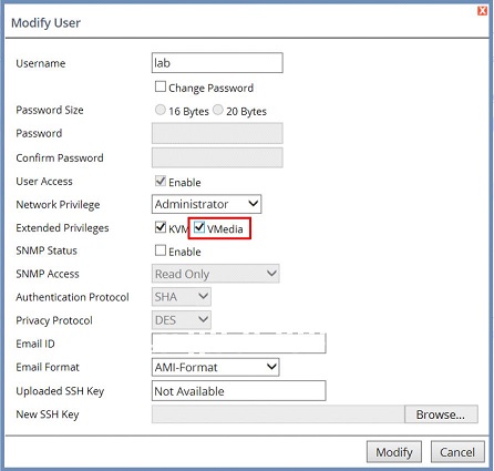
- Select the user name that you created for the BMC, then click Modify User.
- In the Modify User dialog, select the
VMedia check box to add it to the extended
privileges for the user, then click Modify.
- Open a Java-enabled web browser within your LAN and go to
http://IPMI-IP-address/,
then log in.
- Set up the ISO image as virtual media.
- From the top menu, click Remote Control and select
Console Redirection.
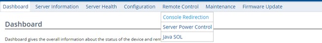
- Click Java Console to open the remote JViewer window. Make sure pop-up blockers are disabled for this site.
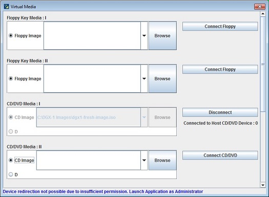
- From the JViewer top menu bar, click Media and then select Virtual Media Wizard.
- From the CD/DVD Media: I section of the
Virtual Media dialog, click
Browse and then locate the re-image ISO file
and click Open.
You can ignore the device redirection warning at the bottom of the Virtual Media wizard as it does not affect the ability to re-image the system.
- Click Connect CD/DVD, then click
OK at the Information
dialog.
The Virtual Media window shows that the ISO image is connected.
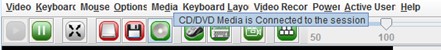
- Close the window.
The CD ROM icon in the menu bar turns green to indicate that the ISO image is attached.
- From the top menu, click Remote Control and select
Console Redirection.
- Reboot, install the image, and complete the DGX-1 setup.
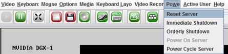
- From the top menu, click Power and then select
Reset Server.
- Click Yes and then OK at the Power Control dialogs, then wait for the system to power down and then come back online.
- At the boot selection screen, select Install DGX
Server.
If you are an advanced user who is not using the RAID disks as cache and want to keep data on the RAID disks, then select Install DGX Server without formatting RAID. See the section Retaining the RAID Partition While Installing the OS for more information.
- Press Enter.
The DGX-1 will reboot from CDROM0 1.00, and proceed to install the image. This can take approximately 15 minutes.
Note: The Mellanox InfiniBand driver installation may take up to 10 minutes.After the installation is completed, the system ejects the virtual CD and then reboots into the OS.
- From the top menu, click Power and then select
Reset Server.

Creating a Bootable Installation Medium
After obtaining an ISO file that contains the DGX OS Server software image from NVIDIA Enterprise Support, create a bootable installation medium, such as a USB flash drive or DVD-ROM, that contains the image.
- If you are creating a bootable USB flash drive, follow the instructions for the
platform that you are using:
- On a text-only Linux distribution, see Creating a Bootable USB Flash Drive by Using the dd Command.
- On Windows, see Creating a Bootable USB Flash Drive by Using Akeo Rufus.
- If you are creating a bootable DVD-ROM, you can use any of the methods described
in Burning the ISO on to a DVD on the Ubuntu
Community Help Wiki.
Note: The ISO file that contains software image for some DGX OS Server releases is greater than the 4.7 GB capacity of a single-layer DVD-ROM. You cannot install these releases from a bootable DVD-ROM because installation of DGX OS Server from a dual-layer DVD-ROM is not supported. Check the size of the ISO file that contains the DGX OS Server software image before creating a bootable DVD-ROM.
Creating a Bootable USB Flash Drive by Using the dd Command
On a Linux system, you can use the dd command to create a bootable USB flash drive that contains the DGX-1 software image.
Ensure that the following prerequisites are met:
- The correct DGX-1 software image is saved to your local disk. For more information, see Obtaining the DGX-1 Software ISO Image and Checksum File.
- The USB flash drive meets these requirements:
- The USB flash drive has a capacity of at least 8 GB.
- The partition scheme on the USB flash drive is a GPT partition scheme for UEFI.
- Plug the USB flash drive into one of the USB ports of your Linux system.
- Obtain the device name of the USB flash drive by running the lsblk command.
lsblk
You can identify the USB flash drive from its size, which is much smaller than the size of the SSDs in the DGX-1, and from the mount points of any partitions on the drive, which are under /media.
In the following example, the device name of the USB flash drive is sde.
~$ lsblk
NAME   MAJ:MIN RM   SIZE RO TYPE MOUNTPOINT
sda      8:0    0   1.8T  0 disk
|_sda1   8:1    0   121M  0 part /boot/efi
|_sda2   8:2    0   1.8T  0 part /
sdb      8:16   0   1.8T  0 disk
|_sdb1   8:17   0   1.8T  0 part
sdc      8:32   0   1.8T  0 disk
sdd      8:48   0   1.8T  0 disk
sde      8:64   1   7.6G  0 disk
|_sde1   8:65   1   7.6G  0 part /media/deeplearner/DGXSTATION
~$
- As root, convert and copy the image to the USB flash drive.
sudo dd if=path-to-software-image bs=2048 of=usb-drive-device-name
CAUTION:The dd command erases all data on the device that you specify in the of option of the command. To avoid losing data, ensure that you specify the correct path to the USB flash drive.
Creating a Bootable USB Flash Drive by Using Akeo Rufus
On a Windows system, you can use the Akeo Reliable USB Formatting Utility (Rufus) to create a bootable USB flash drive that contains the DGX OS software image.
Ensure that the following prerequisites are met:
- The correct DGX OS software image is saved to your local disk. For more information, see Obtaining the DGX-1 Software ISO Image and Checksum File.
- The USB flash drive has a capacity of at least 8 GB.
- Plug the USB flash drive into one of the USB ports of your Windows system.
- Download and launch the Akeo Reliable USB Formatting Utility (Rufus).
- In Drive Properties, select the following
options:.
- In Boot selection, click SELECT, locate, and select the DGX OS software image.
- In Partition scheme, select GPT.
- In Target System, select UEFI (non CSM).
- In Format Options, select the following options:
- In File system, select NTFS.
- In Cluster Size, select 4096 bytes (Default).
- Click Start.
Because the image is a hybrid ISO file, you are prompted to select
whether to write the image in ISO Image (file copy) mode or DD Image (disk
image) mode.
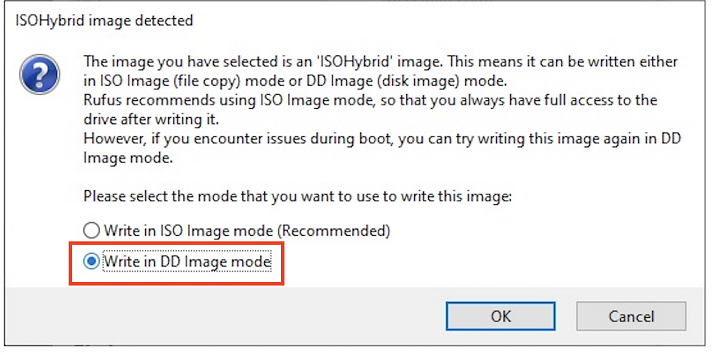
- Select Write in ISO Image mode and click OK.
Re-Imaging the System From a USB Flash Drive
These instructions describe how to re-image the system from a USB flash drive. For information about how to restore the system remotely, see Re-Imaging the System Remotely.
Before re-imaging the system from a USB flash drive, ensure that you have a bootable USB flash drive that contains the current DGX-1 software image.
- Plug the USB flash drive containing the OS image into the DGX-1.
- Connect a monitor and keyboard directly to the DGX-1.
- Boot the system and press F11 when the NVIDIA logo appears to get to the boot menu.
- Select the USB volume name that corresponds to the inserted USB flash drive, and boot the system from it.
- When the system boots up, select one of the following options from the GRUB
menu.
- Install DGX OS <version>: Install DGX OS and reformat data RAID
- Install DGX OS <version> Without Reformatting Data RAID
- Advanced Installation Options: Select if you want to install with an
encrypted root filesystem, then select one of the following options.
- Install DGX OS <version> With Encrypted Root
- Install DGX OS <version> With Encrypted Root and Without Reformatting Data RAID
If you are an advanced user who is not using the RAID disks as cache and want to keep data on the RAID disks, then select the option that contains Without Reformatting RAID. See the section Retaining the RAID Partition While Installing the OS for more information.
- Press Enter.
The DGX-1 will reboot and proceed to install the image. This can take more than 15 minutes.
After the installation is completed, the system then reboots into the OS.
Retaining the RAID Partition While Installing the OS
The re-imaging process creates a fresh installation of the DGX OS. During the OS installation or re-image process, you are presented with a boot menu when booting the installer image. The default selection is Install DGX Software. The installation process then repartitions all the SSDs, including the OS SSD as well as the RAID SSDs, and the RAID array is mounted as /raid. This overwrites any data or file systems that may exist on the OS disk as well as the RAID disks.
Since the RAID array on the DGX-1 is intended to be used as a cache and not for long-term data storage, this should not be disruptive. However, if you are an advanced user and have set up the disks for a non-cache purpose and want to keep the data on those drives, then select the Install DGX Server without formatting RAID option at the boot menu during the boot installation. This option retains data on the RAID disks and performs the following:
- Installs the cache daemon but leaves it disabled by commenting out the RUN=yes line in /etc/default/cachefilesd.
- Creates a /raid directory, leaves it out of the file system table by commenting out the entry containing “/raid” in /etc/fstab.
- Does not format the RAID disks.
- Uncomment the #RUN=yes line in /etc/default/cachefilesd.
- Uncomment the /raid line in etc/fstab.
- Run the following:
- Mount /raid.
sudo mount /raid
- Reload the systemd manager configuration.
systemctl daemon-reload
- Start the cache daemon.
systemctl start cachefilesd.server
- Mount /raid.
These changes are preserved across system reboots.
Updating the System BIOS
You can update the system BIOS remotely through the BMC. Before updating the system BIOS, the system must be turned off through the BMC according to the instructions in this section.
- Obtain the BIOS image.
- Log on to NVIDIA Enterprise Support and click the Announcements tab to locate the DGX-1 software image archive.
- Download the image archive and then extract the .bin file.
- Log on to the BMC and shut down the DGX-1.
- Open a Java-enabled web browser within your LAN and go to
http://<IPMI-IP-address>/, then log in.
Use Firefox or Internet Explorer. Google Chrome is not officially supported by the BMC.
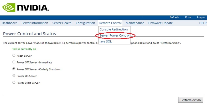
- From the top menu, click Remote Control and then select Server Power Control.
- At the Power Control and Status screen, select the Power Off Server -
Orderly Shutdown option, then click Perform Action.
You can verify that the DGX-1 is shut down by noting that all the Power Control and Status options are grayed out except for the Power On Server option.
- Open a Java-enabled web browser within your LAN and go to
http://<IPMI-IP-address>/, then log in.
- Update the system BIOS.
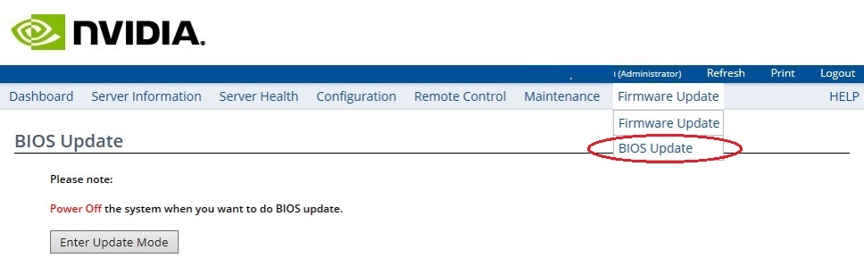
- From the top menu, click Firmware Update, select BIOS Update, and then click Enter Update Mode.
- Click OK at the Are you sure to enter update mode? dialog.
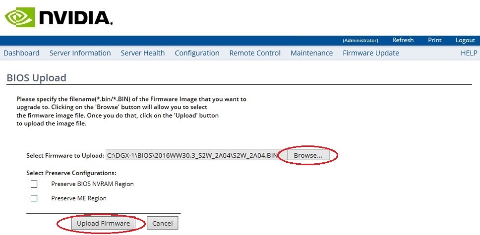
- From the BIOS Upload screen, click Browse at the Select Firmware to Upload step, then navigate the explorer windows to locate the file you downloaded and select it.
- Be sure all the check boxes under Select Preserve Configuration are cleared. This ensures that the BIOS reverts to its fail-safe default settings for a reliable update.
- Click Upload Firmware to start the process of installing the updated
BIOS.
You are asked to wait while the image is verified.
- Click OK at the Proceed? dialog to start the actual upgrade
process.
The BIOS Flash Status screen shows the upgrade progress, which should take a couple of minutes to complete.
Note: Do not interrupt the upgrade process once it has started.
- After the upgrade process has completed, you can use the top menu to turn the
system back on.
- From the top menu, click Remote Control and then select Server Power Control.
- Select the Power On Server option, and then click Perform Action.
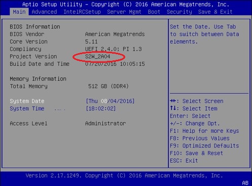
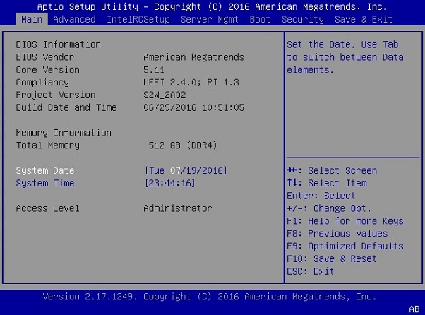
- To verify that the BIOS was updated with the proper file, press [F2] or [Del] to enter the BIOS setup screen when the system reboots, then compare the Project Version with the update filename.
Updating the BMC
You can update the BMC remotely using the IPMI port. Applications can be left running. Power must be left on.
- Obtain the BMC image.
- Log on to NVIDIA Enterprise Support and click the Announcements tab to locate the DGX-1 software image archive.
- Download the image file.
- Open a Java-enabled web browser within your LAN and go to http://<IPMI IP
address>/, then log in to the BMC.
Use Firefox or Internet Explorer. Google Chrome is not officially supported by the BMC.
- If you’re using DHCP and choose not to preserve the network configuration, then
obtain the MAC address for the BMC.
If the BMC is connected to a network via DHCP, the IP address could change after the update. Follow these substeps to obtain the MAC address in order to connect to the BMC after the update, in case the IP address changes. You can skip these steps if a static IP is used.
- From the top menu, click Configuration and then select Network.
- Note the MAC address.
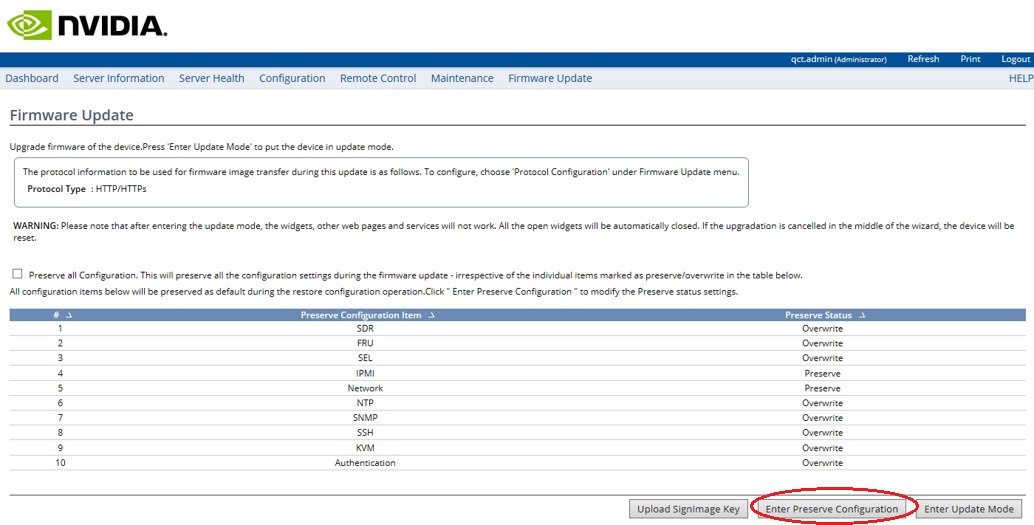
- From the top menu, click Firmware Update and then select Firmware Update from the drop-down menu.
- Click Enter Preserve Configuration, then set the IPMI and Network
preserve status to Preserve and all others to Overwrite.
Note: Be sure to set IPMI to Preserve in order to preserve your BMC login credentials. If you fail to do this, the BMC username/password will be set to qct.admin/qct.admin. If this happens, then be sure to enter the BMC dashboard and go to Configuration->Users to add a new user account and disable the qct.admin account after updating the BMC.
- If necessary, click Firmware Update again from the top menu and then select Firmware Update from the drop-down menu to return to the Firmware Update page.
- Click Enter Update Mode, then click OK at the confirmation
dialog.
After entering Update Mode, aborting the operation or even resizing the browser windows will terminate the session and reset the BMC. If this happens, you will need to close and then reopen the browser to initiate a new session. You may need to wait several minutes for the BMC to reset.
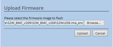
- At the Upload Firmware prompt, click Browse to locate and select
the firmware image file.
Select the encrypted file (the file with the "_enc" suffix on the file extension), as the BMC requires the firmware image to be encrypted.
- Click Upload to transfer the image to the BMC.
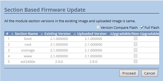
- At the Select Based Firmware Update prompt. select Full Flash and
then click Proceed.
Note:IMPORTANT: Do not shut off power to the DGX-1 while updating the BMC. If the BMC update fails, keep the DGX-1 powered on and booted, and then contact NVIDIA Enterprise Support.
Updating Component Firmware Using the Firmware Update Container
This section provides instructions for updating firmware for the NVIDIA® DGX server BIOS, BMC, and power supplies using a Docker container. This is an alternate method to the instructions provided in the sections Updating the BIOS and Updating the BMC.
General Firmware Update Guidelines
- Before updating the firmware, do the following to prevent corrupting the
firmware due to a system crash or disruption to the update process.
- Ensure the system is healthy
- Stop system activities
- Do not terminate the firmware update console while updating the
firmware.
Component firmware corruption may occur if the update process is interrupted.
- Certain components, such as the system BIOS, requires a system reboot for
the new firmware to take effect.
Reboot the system if prompted.
- In the event of a firmware update failure, gather the follow logs for
failure analysis:
- /var/log/syslog
- /var/log/nvidia-fw.log
Obtaining the Firmware Update Container
- NVSM provides convenient commands to update the firmware using the firmware update container
- Using Docker to run the firmware update container
- Using the .run file which is a self-extracting package embedding the firmware update container tarball
Using NVSM
The NVIDIA DGX-1 system software includes Docker software required to run the container.
- Copy the tar ball to a location on the DGX system.
- From the directory where you copied the tarball file, enter the following
command to load the container image.
$ sudo docker load -i nvfw-dgx1_19.10.7.tar.gz
- To verify that the container image is loaded, enter the following.
$ sudo docker images

REPOSITORY    TAG
nvfw-dg1      19.10.7
- Using NVSM interactive mode, enter the firmware update
module.
$ sudo nvsm
nvsm-> cd systems/localhost/firmware/install
- Set the flags corresponding to the action you want to take.
$ nvsm(/system/localhost/firmware/install)-> set Flags=<option>
See the rest of this chapter for details on individual flags and arguments.
- Run the command.
$ nvsm(/system/localhost/firmware/install)-> start
Using the Tar Ball File
The NVIDIA DGX-1 system software includes Docker software required to run the container.
- Copy the tar ball to a location on the DGX system.
- From the directory where you copied the tarball file, enter the following
command to load the container image.
$ sudo docker load -i nvfw-dgx1_19.10.7.tar.gz
- To verify that the container image is loaded, enter the following.
$ sudo docker images

REPOSITORY    TAG
nvfw-dg1      19.10.7
- Use the following syntax to run the container
image.
$ sudo docker run --rm --privileged -ti -v /:/hostfs nvfw-dgx1:19.10.7 <command> <[arg1] [arg2] ... [argn]
See the rest of this chapter for details on individual flags and arguments.
Using the .run File
Beginning with the firmware container version 19.04.1, a .run file is also available to run the firmware update container. The .run file is a self-extracting package embedding the firmware update container tarball. Using the .run file requires DGX OS Server 4.0.5 or later.
$ chmod +x nvfw-dgx1_19.10.7.run
Use the following syntax to run the container image.
$ sudo nvfw-dgx1_19.10.7.run <command> <[arg1] [arg2] ... [argn]
See the rest of this chapter for details on individual flags and arguments.
Querying the Firmware Manifest
The manifest displays a listing of firmware components embedded in the containers that are qualified by NVIDIA.
To query the firmware manifest, enter the following:
# sudo docker run --rm --privileged -v /:/hostfs <container-repository:tag> show_fw_manifest
Querying the Currently Installed Firmware Versions
Display the onboard firmware version level of each component supported by the container. The output will show which component firmware is up to date, or whether it needs to be updated to the firmware level listed in the manifest.
To query the version information, enter the following.
# sudo docker run --privileged -v /:/hostfs <container-repository:tag> show_version
The output shows the onboard version, the version in the manifest, and whether the firmware is up-to-date.
Updating the Firmware
You can either update all the down-level firmware components at one time, or update just one or more components.
Command Syntax
sudo docker run [-e AUTO=1] --privileged -ti -v /:/hostfs <container-repository:tag> update_fw [-f] <target>
Where <target> specifies the hardware to update, and is either
- all
- to update all firmware components (SBIOS, BMC, and PSU)
or one or more of the following:
- SBIOS
- to update the SBIOS
- BMC
- to update the BMC firmware
- PSU
- to update the power supply units' fimware
The command will scan the specified firmware components and update any that are down-level.
See the section Additional Options for an explanation of the [-e AUTO=1] and [-f] options.
Updating All Firmware Components
- Enter the following.
$ sudo docker run --rm --privileged -ti -v /:/hostfs nvfw-dgx1:19.10.7 update_fw all
The container will scan the components and then prompt for confirmation before starting the update.Following components will be updated with new firmware version: SBIOS BMC IMPORTANT: Firmware update is disruptive and may require system reboot. Stop system activities before performing the update. Ok to proceed with firmware update? <Y/N>
- Press Y to proceed.
When the update completes successfully, the following message is displayed.
Firmware update completed Component: SBIOS, update status: success, reboot required: yes
Component: BMC, update status: success, new version: 3.20.30
- If directed by the update message, reboot the system.
Updating Specific Firmware Components
- Enter the following.
$ sudo docker run --rm --privileged -ti -v /:/hostfs nvfw-dgx1:19.10.7 update_fw PSU
The container will scan the components and then prompt for confirmation before starting the update.Following components will be updated with new firmware version: PSU 1 PSU 2 PSU 3 PSU 4 IMPORTANT: Firmware update is disruptive and may require system reboot. Stop system activities before performing the update. Ok to proceed with firmware update? <Y/N>
- Press Y to proceed.
When the update completes successfully, the following message is displayed.
Firmware update completed
Component: PSU, update status: success, new version: 00.03.07
- If directed by the update message, reboot the system.
Additional Options
Forcing the Firmware Update
To update the firmware regardless of whether it is down-level, use the -f option as follows.
$ sudo docker run --rm --privileged -ti -v /:/hostfs <container-repository:tag> update_fw -f <target>
The container will not check the onboard versions against the manifest.
Updating the Firmware Non-interactively
The standard way to run the container is interactively (-ti option). The container will prompt you to confirm before initiating the update.
To update the firmware without encountering the prompt, use the -eAUTO=1 and -t options as follows.
$ sudo docker run -e AUTO=1 --rm --privileged -ti -v /:/hostfs <container-repository:tag> update_fw <target>
Command Summary
- Show the manifest.
$ sudo docker run --rm --privileged -v /:/hostfs <container-repository:tag> show_fw_manifest
- Show version information.
$ sudo docker run --rm --privileged -v /:/hostfs <ccontainer-repository:tag> show_version
- Check the onboard firmware against the manifest and update any down-level firmware.
$ sudo docker run --rm --privileged -ti -v /:/hostfs <container-repository:tag> update_fw <target>
- Bypass the version check and update the firmware.
$ sudo docker run --rm --privileged -ti -v /:/hostfs <container-repository:tag> update_fw -f <target>
- Update the firmware in non-interactive mode.
$ sudo docker run --rm -e auto=1 --privileged -t -v /:/hostfs <container-repository:tag> update_fw <target>
Removing the Container
Remove the container and image from the DGX server when it is no longer needed. To remove the container and image, enter the following:
$ sudo docker rmi -f <container-repository>
In this case, specify only the container repository and not the tag.
Using the .run File
Beginning with the firmware container version 19.04.1, a .run file is also available to run the firmware update container. The .run file is a self-extracting package embedding the firmware update container tarball. Using the .run file requires DGX OS Server 4.0.5 or later.
- Before using, make the file executible.
$ chmod +x /<run-file-name>.run
- Run the file.
$ sudo ./<run-file-name>.run
This command is the same as running the container with the update_fw all option.
The .run file accepts the same options that are used when running the container.
Examples:
$ sudo ./<run-file-name>.run show_fw_manifest
$ sudo ./<run-file-name>.run show_version
$ sudo ./<run-file-name>.run update_fw <target>
$ sudo ./<run-file-name>.run update_fw -f <target>
Replacing the System and Components
Be sure to familiarize yourself with the NVIDIA Terms & Conditions documents before attempting to perform any modification or repair to the DGX-1. These Terms & Conditions for the DGX-1 can be found through the NVIDIA DGX Systems Support page.
Contact NVIDIA Enterprise Support to obtain an RMA number for any system or component that needs to be returned for repair or replacement. When replacing a component, use only the replacement supplied to you by NVIDIA.
- Solid State Drives (SSDs)
- Power Supplies
- Fan Modules
- DIMMs
- Battery
Return failed high-value components to NVIDIA. You do not need to return low-cost items such as batteries, power supplies, and fans.
Replacing the System
When returning a DGX-1 under RMA, consider the following points.
SSDs
If necessary, you can remove and keep the SSDs prior to shipping the system back for replacement. If you already received a replacement system and you want to keep the original SSDs, install the new SSDs into the defective system when shipping it back.
Bezel
Be sure to include the bezel when returning the system.
Replacing an SSD
Access the SSDs from the front of the DGX-1. You can hot swap the SSDs as follows:
- If not already removed, remove the bezel by grasping the bezel by the side
handles and then pulling the bezel straight off the front of the DGX-1. Note:CAUTION: Be careful not to accidentally press the power button that is on the right edge of the DGX-1 when removing or installing the bezel.
- Locate the SDD that you want to replace, then press the round button at the top edge to release the latch.
- Pull the latch down and then out to unseat the SSD assembly.
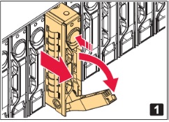
- Continue pulling the SSD assembly to completely remove it from the unit.
- Using a phillips screwdriver, remove the four screws attaching the SSD to the
hot-swap tray.
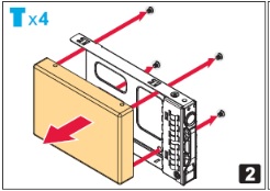
- Save the screws for the replacement.
- Mount the replacement SSD to the hot-swap tray using the four screws. Make sure that the connector is on the open edge side of the tray.
- With the round button at the top, insert the assembly into the appropriate bay, then push the assembly all the way in.
- Press the latch against the assembly to completely seat the assembly.
- Reattach the bezel.
With the bezel positioned so that the NVIDIA logo is visible from the front and is on the left-hand side, line up the pins near the corners of the DGX-1 with the holes in back of the bezel, then gently press the bezel against the DGX-1. The bezel is held in place magnetically.
Note:CAUTION: Be careful not to accidentally press the power button that is on the right edge of the DGX-1 when removing or installing the bezel.
Recreating the Virtual Drives
After you have replaced the OS SSD, with or without any of the cache SSDs, you need to recreate the virtual drives and then re-image the system in order to recreate the partitions on all the virtual drives.
The following is an overview of the process:
- Clear the drive group configuration
- Recreate the OS Virtual Drive
- Recreate the Cache Virtual Drive
- Re-image the System
These instructions apply only if you have replaced the OS SSD, with or without one or more of the cache SSDs. If you have replaced only one or more of the cache SSDs, and not the OS SSD, then follow the instructions in the section Recreating the RAID 0 Array
Access the BIOS Setup Utility
RAID configuration is accomplished through the BIOS setup utility.
- Connect a display (1024x768 or lower resolution) and keyboard to the DGX-1.
- Turn the DGX-1 on or reboot.
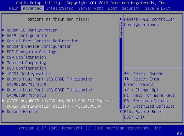
- At the NVIDIA logo boot screen, press [F2] or [Del] to enter the BIOS setup screen.
- Select the Advanced tab from the top menu and then Scroll down and select the MegaRAID Configuration Utility. The RAID Configuration menu appears.
If you replaced the OS drive, follow the instructions in the section Clear the Drive Group Configuration .
Clear the Drive Group Configuration
These instructions apply when you have replaced the OS drive.
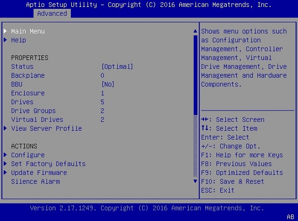
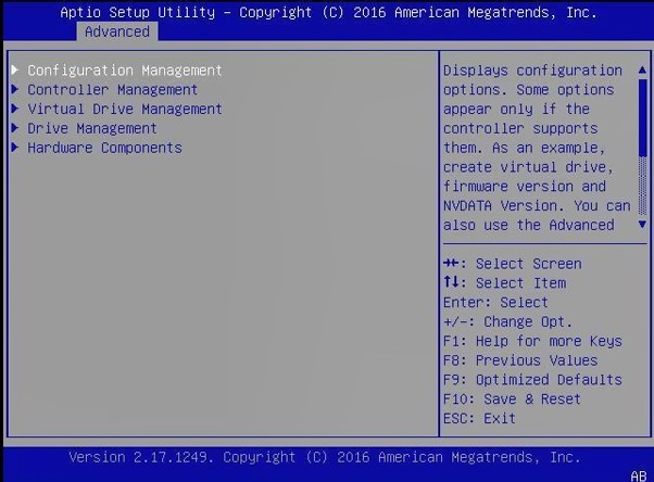
- Select Main Menu, then select Configuration Management.
- Select Clear Configuration.
- Select Confirm [Disabled] and then select Enabled at the confirmation popup.
- Select Yes, then select OK at the success screen.
- Follow the instructions in the sections Recreate the OS Virtual Drive and then Recreate the RAID0 Virtual Drive .
Recreate the OS Virtual Drive
These instructions apply when you have replaced the OS drive. Be sure to first complete the instructions in the section Clear the Drive Group Configuration.
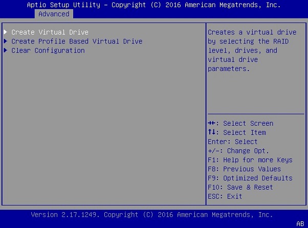
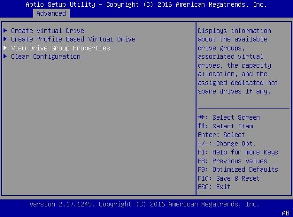
- Navigate to the RAID Utility Main Menu, then under Actions, select Configure, then select Configuration Management.
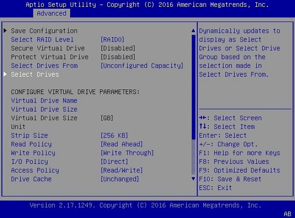
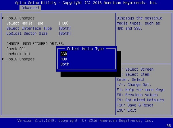
- Select Create Virtual Drive, then select Select Drives at the next screen. Leave all other options at their default settings as shown below. The list of drives under CHOOSE UNCONFIGURED DRIVES will initially be empty.
- To view the available drives, select Select Media Type [HDD], then change to [SSD].
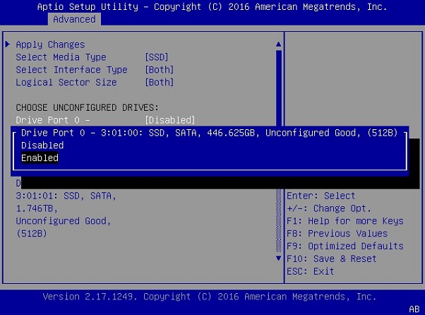
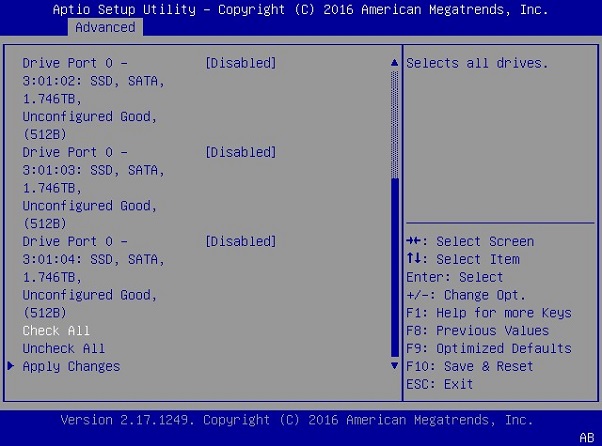
- Under CHOOSE UNCONFIGURED DRIVES, select the 446 GB drive, then change to [Enabled] at the pop-up dialog.
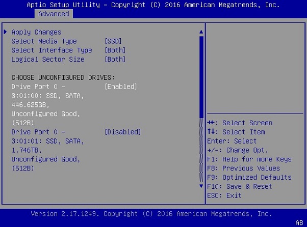
- Confirm that only the first drive at Drive Port 0 - 3:01:00 displays as [Enabled].
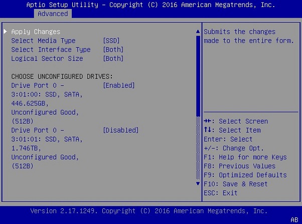
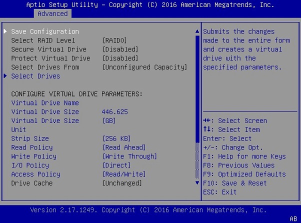
- Scroll up and select Apply Changes.
- Select OK at the success screen. The virtual drive creation page now displays a summary of your selection. The Virtual Drive Size should be approximately 446 GB.
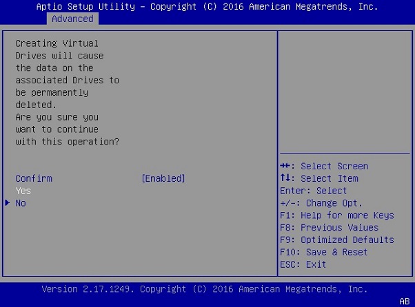
- Select Save Configuration at the top of the menu.
- Change the Confirm [Disabled] field to [Enabled] and then select [Yes].
- Select [OK] at the success screen. You have successfully re-created Virtual Drive 0, where the OS will be installed.
- Follow the instructions in the section Recreate the RAID0 Virtual Drive
Recreate the RAID0 Virtual Drive
These instructions apply when you have replaced the OS drive and cleared the drive group configuration.
- Navigate to the RAID Utility Main Menu, then under Action, select Configure, then select Configuration Management.
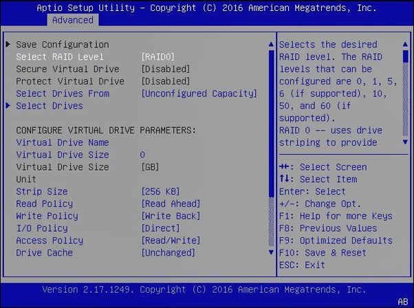
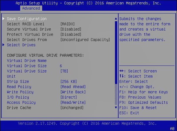
- Select Create Virtual Drive.
- Scroll to Select RAID Level and switch to [RAID0], if not already set.
- Scroll to Select Media Type and switch to [SSD].
- Select Select Drives.
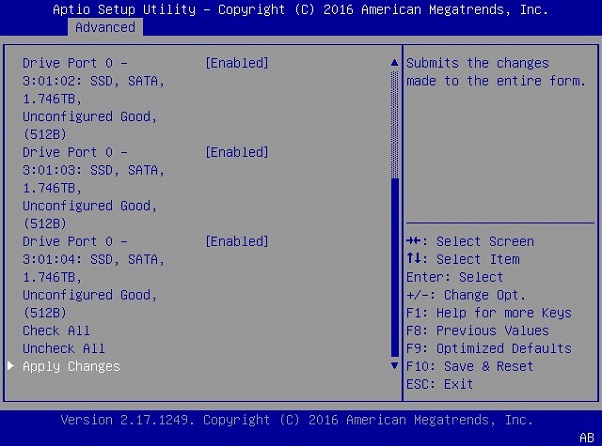
- Switch all unconfigured 1TB drives to [Enabled].
- Select Apply Changes.
- Change Confirm to [Enabled], then select Yes.
- Select OK at the success screen. The Create Virtual Drive screen displays a summary of your selection.
- Verify that the summary matches your selection, then select Save Configuration.
- Make sure Confirm is set to [Enabled], then select Yes to confirm the change.
- Select OK at the success screen.
- Confirm and exit.
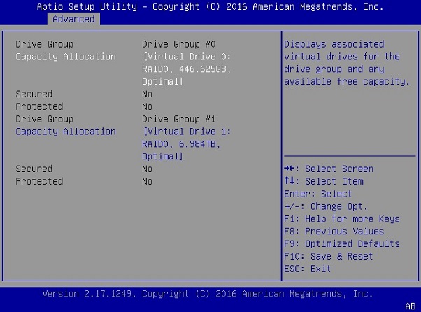
- Select View Drive Group Properties to confirm the configuration.
- Verify that your configuration screen shows that you have two virtual drives with the following properties: Virtual Drive 0 of size 446 GB (or very similar) Virtual Drive 1 of size 7 TB (or very similar).
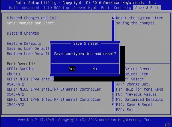
- If your Drive Groups match the above, press [F10] to save these settings and reset the system.
- Select Save Changes and Reset, then select Yes at the confirmation prompt.
- Follow the instructions in the section Restoring the DGX-1 Software Image to create the partitions.
Recreating the RAID 0 Array
- Run the script by entering the following on the command line:
$ sudo python /usr/bin/configure_raid_array.py -c -f
- After the script has finished recreating the RAID 0 array, reboot the DGX-1 to verify that /raid is mounted and usable.
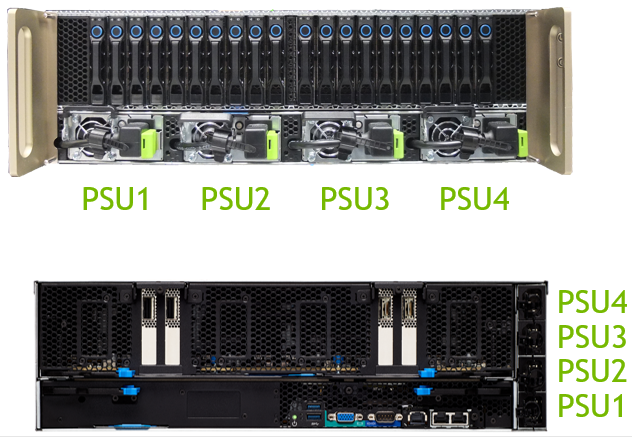
Replacing the Power Supplies
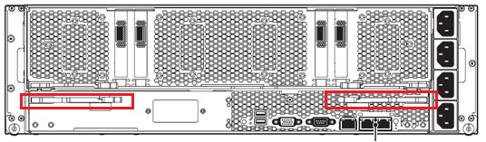
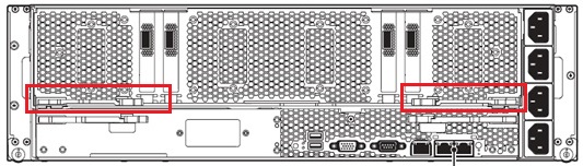
Access the power supplies from the front of the DGX-1. Use the following diagram to assist in identifying each PSU - the IDs correspond to how the PSUs are identified in the BMC.The top image shows the PSUs and the bottom image shows the corresponding power cord position for each PSU.
You can hot-swap the power supplies as follows:
- If not already removed, remove the bezel by grasping the bezel by the side
handles and then pulling the bezel straight off the front of the DGX-1. CAUTION:Be careful not to accidentally press the power button that is on the right edge of the DGX-1 when removing or installing the bezel.
- Unplug the power cord from the power connector on the fan assembly.
- Flip the power supply handle out.
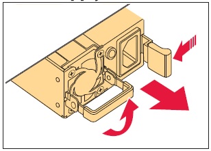
- Push the green release lever to the left and simultaneously use the power supply handle to pull out the power supply.
- Slide the replacement power supply into the bay and push until seated.
- Flip the power supply handle up against the power supply.
- Reconnect the power cord.Note:IMPORTANT: Make sure that the end of the power cord cable tie is not inserted into the power supply fan. The cable tie can interfere with normal operation of the fan, resulting in failure of the power supply.
- Reattach the bezel.
With the bezel positioned so that the NVIDIA logo is visible from the front
and is on the left-hand side, line up the pins near the corners of the DGX-1 with
the holes in back of the bezel, then gently press the bezel against the DGX-1. The
bezel is held in place magnetically.
Note:CAUTION: Be careful not to accidentally press the power button that is on the right edge of the DGX-1 when removing or installing the bezel.
Replacing the Fan Module
CAUTION: To avoid overheating the system, the fan module should be replaced within 25 seconds after removal.
- Unscrew the thumbscrews at the front of the DGX-1, then slide the DGX-1 about half way out from the rack.
- Squeeze together the latches at the square access openings on the top of the
chassis, then flip open the top of the chassis to expose the fan modules.
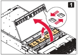
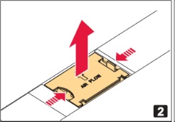
- Squeeze the release tabs on the outer edge of the fan module you want to
replace, then pull up to lift the fan module out of the unit.
- Replace with a new fan module using the reverse steps.
Replacing the Battery
The battery is located on the motherboard tray, which is accessible from the rear of the DGX-1.

- Turn off the DGX-1 and disconnect all network and power cabling.
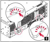
- Remove the motherboard tray.
- Locate the locking levers for the motherboard tray at the rear of the
DGX-1.
There are two sets of locking levers. The locking levers for the motherboard are the bottom set.
- Rotate the retention clasps inward towards the center of the
unit.
The retention clasps hold the locking levers in place. Rotating the clasps inward releases the locking levers.
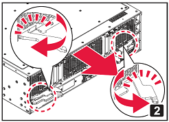
- Swing the locking levers out and then use them to pull the motherboard tray out of the unit.Do not pull the unit by the blue retention clasps; they may break.
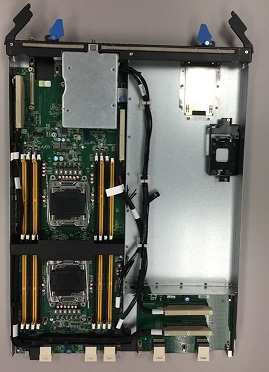
- Set the motherboard tray on a clean work surface, and position it so
that the locking levers are at the top as you look down on the
tray.
The battery is located at the upper left of the tray, near the edge.
- Locate the locking levers for the motherboard tray at the rear of the
DGX-1.
- Remove the battery.
Gently push the battery to the right, then lift it off the board.
- Install the new CR2032 battery.
With the "+" symbol on the right side of the battery facing the PCI bus cables, insert the battery at an angle into the slot, then gently push the battery to the left and into place.
- Carefully insert the motherboard tray back into the unit, then swing the locking levers flat against the tray and secure them in place with the retention clasps.
- Install all network and power cables.
- Power on the system, then press [F2] or [Del] to enter the BIOS setup screen.
- Navigate to the Main tab, then if necessary, set the System Date and System Time and then press [F10] to save the settings and reboot.
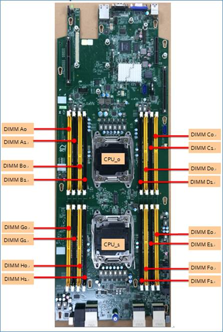
Replacing the DIMMs
Before attempting to replace any of the dual inline memory modules (DIMMs), make sure that you know the location of the faulty DIMM needing replacment. The location ID is an alpha-numeric designator, such as A0, A1, B0, B1, etc., and is reported in the BMC log files.
The DIMMs are located on the motherboard tray, which is accessible from the rear of the DGX-1.
- Turn off the DGX-1 and disconnect all network and power cabling.
- Remove the motherboard tray.
- Locate the locking levers for the motherboard tray at the rear of the DGX-1. There are two sets of locking levers. The locking levers for the motherboard are the bottom set.
- Rotate the retention clasps inward towards the center of the unit. The retention clasps hold the locking levers in place. Rotating the clasps inward releases the locking levers.
- Swing the locking levers out and then use them to pull the motherboard tray out of the unit.Do not pull the unit by the blue retention clasps; they may break.
- Set the motherboard tray on a clean work surface, and position it so that the locking levers are at the top as you look down on the tray. The DIMMs are on a printed circuit board on the left side of the tray.
- Using the figure below as a guide, locate the DIMM corresponding to the ID of the faulty DIMM as reported in the BMC log.
- Remove the DIMM.
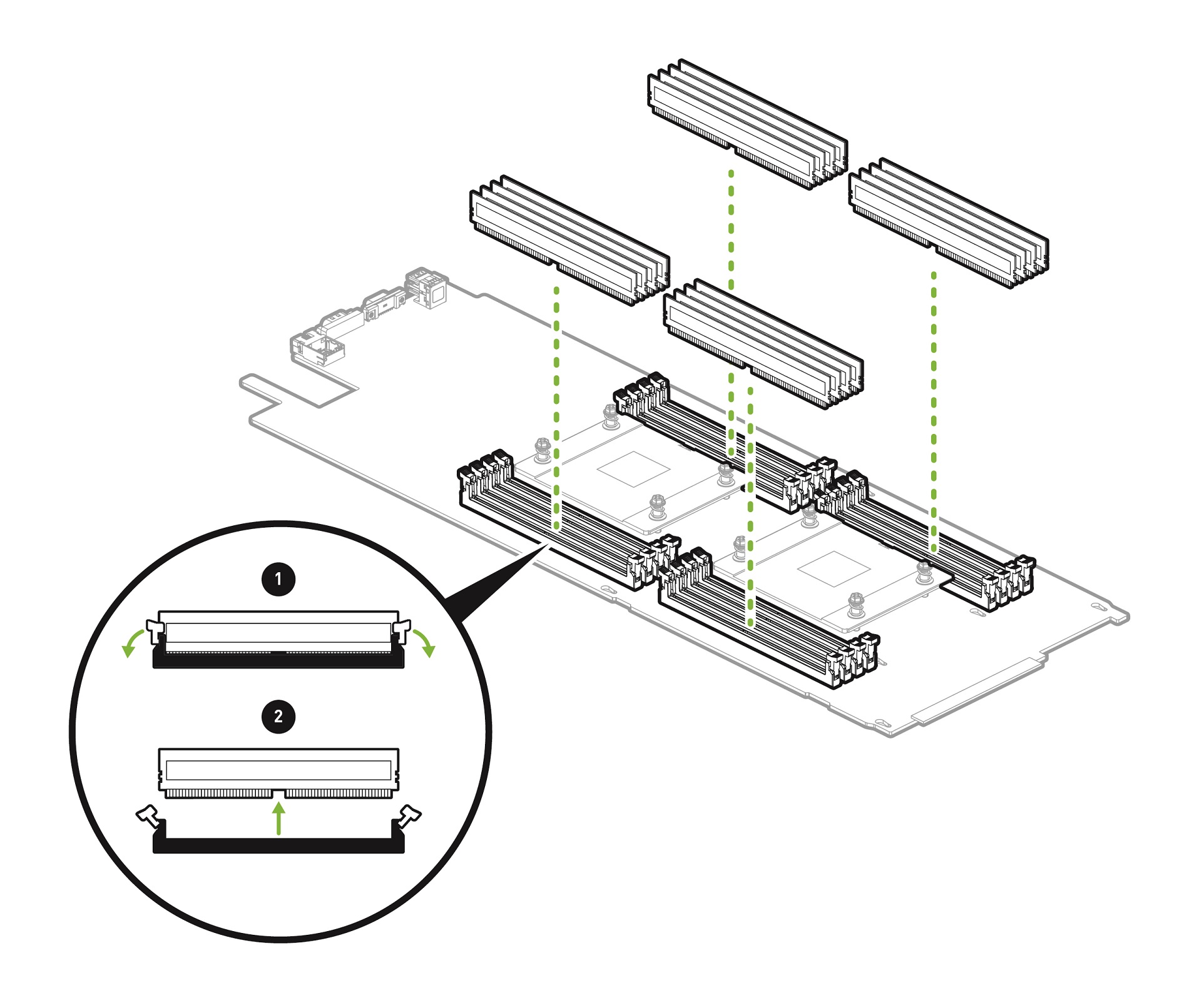
- Press down on the side latches at both ends of the DIMM socket to push them away from the DIMM. This should unseat the DIMM from the socket.
- Pull the DIMM straight up to remove it from the socket.
- Carefully insert the replacement DIMM.

- Make sure the socket latches are open.
- Positon the DIMM over the socket, making sure that the notch on the DIMM lines up with the key in the slot, then press the DIMM down into the socket until the side latches click in place.
- Make sure that the latches are up and locked in place.
- Carefully insert the motherboard tray back into the unit, then swing the locking levers flat against the tray and secure them in place with the retention clasps.
Installing/Replacing the 10GbE Mezzanine SPF+ NIC
- Turn off the DGX-1 server and disconnect all network and power cabling.
- Remove the motherboard tray.
- Locate the locking levers for the motherboard tray at the rear of the DGX-1. There are two sets of locking levers. The locking levers for the motherboard are the bottom set.
- Rotate the retention clasps inward towards the center of the unit. The retention clasps hold the locking levers in place. Rotating the clasps inward releases the locking levers.
- Swing the locking levers out and then use them to pull the motherboard tray out of the unit.Do not pull the unit by the blue retention clasps; they may break.
- Set the motherboard tray on a clean, static-free work surface.
- Replace the NIC.
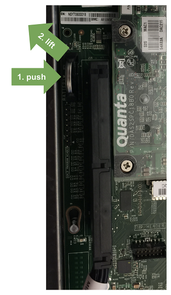
- Locate the NIC.
The 10G NIC is located in the corner of the motherboard tray, by the locking levers. Look for the white Quanta label on the sikscreen.
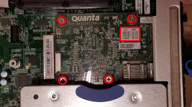
- Remove the four screws as identified in the previous image, then gently lift the NIC off the motherboard..
- Line up the new NIC so that the pins of the card are over the mezzanine connector on the motherboard, then gently press down until the card reaches the bottom..
- Reinstall the four screws to secure the card to the motherboard.
- Carefully insert the motherboard tray back into the unit, then swing the locking levers flat against the tray and secure them in place with the retention clasps.
- Reconnect all cables and apply power to the system.
- Locate the NIC.
- Validate the installation.
- Check that there are no BMC errors.
- Validate Ethernet connectivity.
Check the Link and Speed LEDs on the 10G NIC card to see if the link is active (amber Link LED - left-side) and 10Gb/s (green Speed LED - right-side).
Use the following command to check if the 10G NIC card is recognized at the OS level.
# lspci -nn | grep net
Use the following commands to check if the device is up, to check the status, and to verify that the MTU setting is correct.
# ip link show <device>
# ifconfig <device>
# ethtool -i <device>
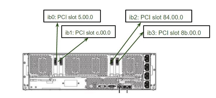
Replacing the InfiniBand Cards
The InfiniBand cards are located on the GPU tray which is accessible from the rear of the DGX-1. Be sure you have identified the faulty InfiniBand card needing to be replaced. The slots are identified as indicated in the following image.
lspci | grep -i Mellanox
Output for model CX455A
05:00.0 Infiniband controller: Mellanox Technologies MT27700 Family [ConnectX-4]
0c:00.0 Infiniband controller: Mellanox Technologies MT27700 Family [ConnectX-4]
84:00.0 Infiniband controller: Mellanox Technologies MT27700 Family [ConnectX-4]
8b:00.0 Infiniband controller: Mellanox Technologies MT27700 Family [ConnectX-4]
Output for model CX555A
05:00.0 Infiniband controller: Mellanox Technologies MT27800 Family [ConnectX-5]
0c:00.0 Infiniband controller: Mellanox Technologies MT27800 Family [ConnectX-5]
84:00.0 Infiniband controller: Mellanox Technologies MT27800 Family [ConnectX-5]
8b:00.0 Infiniband controller: Mellanox Technologies MT27800 Family [ConnectX-5]
- Turn off the DGX-1 and disconnect all network and power cabling.
- Remove the GPU tray.
- Locate the locking levers for the GPU tray at the rear of the DGX-1. There are two sets of locking levers. The locking levers for the GPU tray are the top set.
- Rotate the retention clasps inward towards the center of the unit. The retention clasps hold the locking levers in place. Rotating the clasps inward releases the locking levers.
- Swing the locking levers out and then use then to pull the GPU tray out of the unit.Do not pull the unit by the blue retention clasps; they may break.
- Set the GPU tray on a clean work surface.
WARNING: Do not attempt to move or lift the GPU tray by grabbing the
U-bolts.
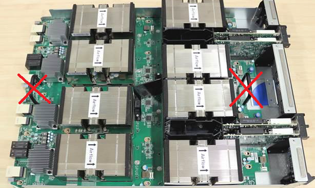
To properly move the GPU tray, grab the tray by the outer edges of the assembly and support it from underneath, taking care not to damage any components.
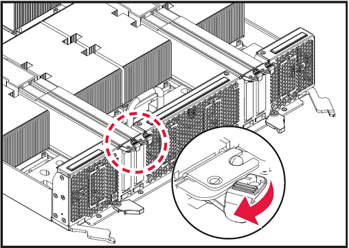
- At the top edge of the bracket for the InfiniBand card that you want to replace, rotate the retention clasp to free the bracket.
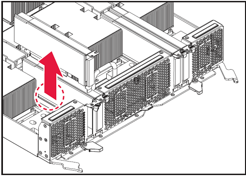
- Firmly grasp the InfiniBand card and lift it straight up out of the PCIe slot.
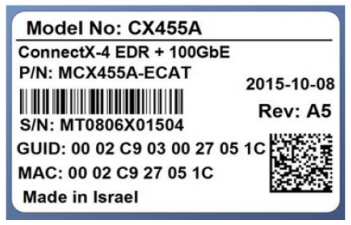
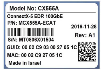
- Compare the physical label on the removed card with the label on the replacment card to make sure they are the same model.
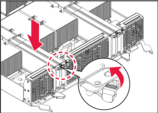
- Position the replacement InfiniBand card over the empty PCIe slot and insert it into the slot.
- Swing the retention clasp over the bracket to secure the bracket in place.
- Carefully insert the GPU tray back into the unit, then swing the locking levers flat against the tray and secure them in place with the retention clasps.
- Reconnect all connectors, boot the system, then perform the verification and setup steps described in the next section.
Setting Up the InfiniBand Cards
This section describes the steps needed to verify that the InfiniBand card has been replaced correctly.
- With the DGX-1 turned on, verify that the card was installed correctly and is
recognized by the system.
$ lspci | grep -i mellanox
The output should show all four InfiniBand cards.Example
 05:00.0 Infiniband controller: Mellanox Technologies MT27700 Family [ConnectX-4]
 0c:00.0 Infiniband controller: Mellanox Technologies MT27700 Family [ConnectX-4]
 84:00.0 Infiniband controller: Mellanox Technologies MT27700 Family [ConnectX-4]
 8b:00.0 Infiniband controller: Mellanox Technologies MT27700 Family [ConnectX-4]
If all four cards are not reported, then the card was not installed properly and should be reseated. If a card other than the officially supported Mellanox family of adapters appears, contact NVIDIA Enterprise Support. - Verify that the InfiniBand drivers are present.
$ lsmod | grep -i ib_
The output should be a list of lb_ and mlx_ driver components.Example
 ib_ucm 20480 0
 ib_ipoib 131072 0
 ib_cm 45056 3 rdma_cm,ib_ucm,ib_ipoib
 ib_uverbs 73728 2 ib_ucm,rdma_ucm
 ib_umad 24576 0
 mlx5_ib 192512 0
 mlx4_ib 192512 0
 ib_sa 36864 5 rdma_cm,ib_cm,mlx4_ib,rdma_ucm,ib_ipoib
 ib_mad 57344 4 ib_cm,ib_sa,mlx4_ib,ib_umad
 ib_core 143360 13 rdma_cm,ib_cm,ib_sa,iw_cm,nv_peer_mem,mlx4_ib,mlx5_ib,ib_mad,ib_ucm,ib_umad,ib_uverbs,rdma_ucm,ib_ipoib
 ib_addr 20480 3 rdma_cm,ib_core,rdma_ucm
 ib_netlink 16384 3 rdma_cm,iw_cm,ib_addr
 mlx4_core 344064 2 mlx4_en,mlx4_ib
 mlx5_core 524288 1 mlx5_ib
 mlx_compat 16384 18 rdma_cm,ib_cm,ib_sa,iw_cm,mlx4_en,mlx4_ib,mlx5_ib,ib_mad,ib_ucm,ib_netlink,ib_addr,ib_core,ib_umad,ib_uverbs,mlx4_core,mlx5_core,rdma_ucm,ib_ipoib
- Verify that the OFED software was installed correctly.
$ modinfo mlx5_core | grep -i version | head -1
Example output:Version : 3.4-1.0.0
Note: DGX OS Server release 1.x should have OFED software 3.2.
DGX OS Server release 2.x should have OFED software 3.4.
DGX OS Server release 3.x should have OFED software 4.0.
DGX OS Server release 4.x should have OFED software 4.4. - Restart the InfiniBand services so that the new card is recognized.
- Restart the InfiniBand service.
$ sudo service openibd restart
- Verify that the service has started.
$ service openibd status
  openibd start/running
- If the services do not start, verify
- That the drivers are loaded according to step 3.
- That the associated cables are connected to the InfiniBand ports.
- The state of ibstat (refer to step 7)
- Whether errors are reported in /var/log/syslog.
- Restart the InfiniBand service.
- Verify the firmware version.
$ cat /sys/class/infiniband/mlx5*/fw_ver
Example output:12.17.1010 12.17.1010 12.17.1010 12.17.1010
The latest InfiniBand firmware version supported for each DGX OS Server release is as follows:- Release 1.x: Firmware version 12.16.1020
- Release 2.x: Firmware version 12.17.1010
- Release 3.x: Firmware version 12.18.1000
- Release 4.x: Firmware version 12.23.1020
- If you need to update the firmware, follow these steps:
- Initiate the firmware update.
$ sudo /opt/mellanox/mlnx-fw-updater/mlnx_fw_updater.pl
The script will check the firmware version of each card and update where needed. If the firmware is updated for any card, you will need to reboot the system for the changes to take effect. - Reboot the system if instructed.
- After rebooting the system, verify that all the Mellanox InfiniBand
cards are using the current firmware.
$ cat /sys/class/infiniband/mlx5*/fw_ver
 12.17.1010
 12.17.1010
 12.17.1010
 12.17.1010
- Initiate the firmware update.
- Verify the physical port state for the InfiniBand cards.
$ ibstat
In the output text, verify that the Physical State for each card with a cable connection is LinkUp and that the port for the card is configured with a GUID. The following example output shows one card in a non-connected state, and three cards in a connected state. Relevant text is highlighted in bold.CA 'mlx5_0' CA type: MT4115 Number of ports: 1 Firmware version: 12.17.1010 Hardware version: 0 Node GUID: 0x248a0703000de288 System image GUID: 0x248a0703000de288 Port 1: State: Down Physical state: Polling Rate: 10 Base lid: 65535 LMC: 0 SM lid: 0 Capability mask: 0x2651e848 Port GUID: 0x248a0703000de288 Link layer: InfiniBand CA 'mlx5_1' CA type: MT4115 Number of ports: 1 Firmware version: 12.17.1010 Hardware version: 0 Node GUID: 0x248a0703000de26c System image GUID: 0x248a0703000de26c Port 1: State: Initializing Physical state: LinkUp Rate: 100 Base lid: 65535 LMC: 0 SM lid: 0 Capability mask: 0x2651e848 Port GUID: 0x248a0703000de26c Link layer: InfiniBand CA 'mlx5_2' CA type: MT4115 Number of ports: 1 Firmware version: 12.17.1010 Hardware version: 0 Node GUID: 0x248a0703001effde System image GUID: 0x248a0703001effde Port 1: State: Initializing Physical state: LinkUp Rate: 100 Base lid: 65535 LMC: 0 SM lid: 0 Capability mask: 0x2651e848 Port GUID: 0x248a0703001effde Link layer: InfiniBand CA 'mlx5_3' CA type: MT4115 Number of ports: 1 Firmware version: 12.17.1010 Hardware version: 0 Node GUID: 0x7cfe900300118f22 System image GUID: 0x7cfe900300118f22 Port 1: State: Initializing Physical state: LinkUp Rate: 100 Base lid: 65535 LMC: 0 SM lid: 0 Capability mask: 0x2651e848 Port GUID: 0x7cfe900300118f22 Link layer: InfiniBand
Secure Data Deletion of the SSDs
This section explains how to securely delete data from the NVIDIA DGX-1 system SSDs to permanently destroy all the data that was stored there. This performs a more secure SSD data deletion than merely deleting files or reformatting the SSDs.
Method A: Using the MegaRAID Controller
This method uses the on-board MegaRAID controller.
- Boot the NVIDIA DGX-1 server and at the NVIDIA logo boot screen, press [F2] or [Del] to enter the BIOS setup screen.
- Select the Advanced tab from the top menu and then scroll down and select the MegaRAID Configuration Utility.
- Select View Server Profile.
- Select Virtual Drive Management.
- Select Virtual Drive 0.
- Select Operation and press [Enter], then select Delete Virtual Drive.
- Select the "Thorough" erase mode, then select Go and press [Enter].
- Select Confirm and then select Enabled at the Confirm popup.
- Return to the MegaRAID Configuration Utility and perform the same steps, selecting Virtual Drive 1 at step 6.
Method B: Using the StorCLI Secure Erase Commands
This method uses the StorCLI Erase commands. StorCLI should be included in the ISO image that you'll need.
- Boot the system from the ISO image, either remotely or from a bootable USB key.
- At the GRUB menu, choose ‘Rescue a broken system’, then configure the locale and network information.
- When asked to choose a root file system, choose
'Do not use a root file system’
and then
‘Execute a shell in the installer environment’
- Install the StorCLI package.
At the root prompt, issue the following.
# udpkg -i /cdrom/extras/pool/restricted/s/storcli/storcli_1.20.15_all.deb
- Switch to the StorCLI folder.
# cd /opt/MegaRAID/storcli
- Confirm that virtual drives 0 and 1 are in the system (boot and cache volumes
respectively).
# ./storcli64 /c0 /vall show
Example output snippet.
Controller = 0
Status = Success
Description = None

Virtual Drives :
==============
----------------------------------------------------------------------
OC/VD  TYPE   State Access Consist Cache CaC sCC  Size Name
----------------------------------------------------------------------
0/0    RAID0  Opt1  RW     Yes     RWTD   -  ON   446.625 GB
0/1    RAID0  Opt1  RW     Yes     RWTD   -  ON     6.983 TB
...
- Erase the volume /c0 /v0.
- Erase the volume.
# ./storcli64 /c0 /v0 start erase thorough
- Confirm the erase progress.
# ./storcli64 /c0 /v0 show erase
- Erase the volume.
- Erase the volume /c0 /v1 .
This step can be performed even though the previous erase step is still in progress.
- Erase the volume.
# ./storcli64 /c0 /v1 start erase thorough
- Confirm the erase progress.
# ./storcli64 /c0 /v1 show erase
- Erase the volume.