Remove the BlueField-3 I/O Bay#
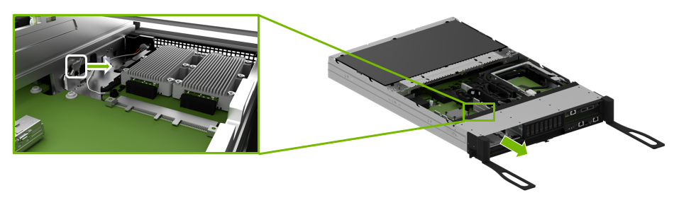
After the four cables have been unplugged, press the left release tab and push the bay towards the front.
Carefully route the cables through the opening as the I/O bay is moved out of the motherboard tray.
Finish pulling the old I/O bay out of the motherboard tray.
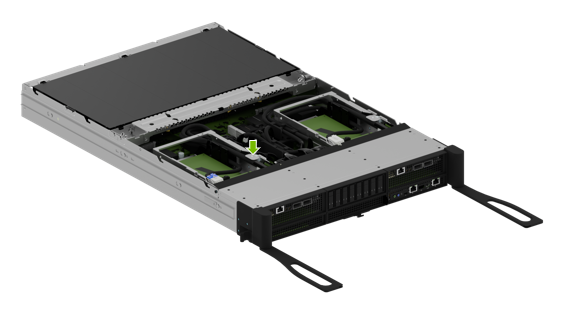
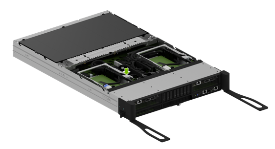
Ensure the motherboard tray levers remain fully extended, as shown in the illustration, so the M.2 bay can be pulled out.
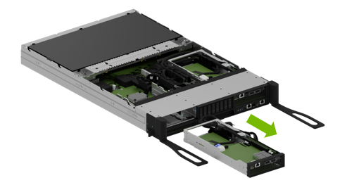
Release the M2 Bay#
Ensure the ejection levers are fully extended to prevent obstruction before removing the M.2 bay from the motherboard.
Release the latch on the M.2 bay as shown in the illustration and then pull the bay out the front to eject it.
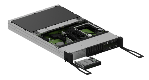
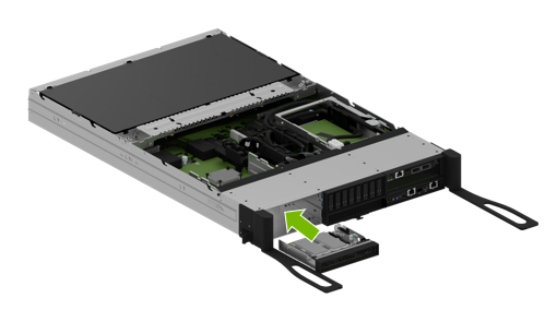
Insert the M.2 Drive Bay and Reconnect the I/O Bay#
After the replacement is complete, ensure the ejection levers are completely open. Insert the M.2 drive bay into the corresponding lower slot until it locks in place.
Carefully route all the cables through the opening in the motherboard tray slot.
After inserting the I/O bay into the tray, ensure it locks in place, checking the tab has locked.
Connect the two power cables and the two PCIe cables to their correct connectors on the switchboard, following the labels on each cable end.
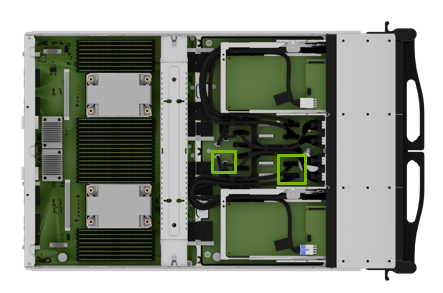
To identify the correct connections, refer to this table that maps BlueField-3 card connectors to their corresponding board connectors.
BlueField-3 I/O Board
Left Slot Installation
Right Slot Installation
Cable Label P2
Board connector J9
Board connector J3
Cable Label P3
Board connector J10
Board connector J4