

Configure HA (High Availability)#
In a cluster with a single head node, the head node is a single point of failure for the entire cluster. In many environments, it is unacceptable for the failure of a single machine to disrupt daily operations.
High Availability (HA) configuration for a head node involves adding a secondary head node to provide redundant head node services. If one head node fails, the other can take over, ensuring service continuity with minimal downtime.
HA is typically configured using shared storage, commonly provided by an NFS service, which serves the /home directory on the active head node, and on the regular nodes. In this case, it will also be configured to provide access to the /cm/shared directory. This ensures that no matter which head node is active, access to these folders can be maintained.
In brief, the steps to be taken are:
Test the connection to the NFS share.
On the primary head node, configure and initialize the HA setup.
On the secondary head node, boot from network into “Rescue” mode and execute the cloning process. Note that the BCM ISO is not required.
Back on the primary head node, finalize the HA setup.
Configure shared storage to use the NFS share.
Test the failover, allowing for rebooting the head nodes sequentially.
Details required to complete this section, with example values used in this guide:
Parameter |
Example Value |
|---|---|
NFS Share |
192.168.255.31:/nvidia-era-bcm-cluster |
HA shared interface name |
bond0:ha |
HA shared internal interface IP address |
192.168.100.254 |
Hostname of secondary head node |
nvidia-era-bcm-02 |
Failover network name |
failovernet |
Failover network base address |
192.168.120.0 |
Failover network netmask |
255.255.255.0 |
Failover network domain name |
failover.cluster |
Failover network interface (primary) |
eth0 |
Failover network IP (primary) |
192.168.120.11 |
Failover network interface (secondary) |
eth0 |
Failover network IP (secondary) |
192.168.120.12 |
IP address for secondary head node |
192.168.100.252 |
Note
Where applicable these values will be displayed in red. Be sure to replace all example values with actual information relevant to the target environment.
Test the Connection to the NFS Share#
Before setting up HA, it is recommended to test the connection to the NFS share. If the share is inaccessible, the node health check will fail, as the /home and /cm/shared directories will not be unavailable.
This test will be performed in two stages. In the first stage, the NFS share will be mounted from the root operating system, where a “ha” directory will be created with a test txt file within it. In the second stage, the ha folder will be mounted from within cmsh, and the test file will be listed to confirm its creation. Two additional directories, home and cmshared, will then be created to map the folders after the main high-availability setup is completed.
Mount the NFS share from the root OS.
a. Exit cmsh and return to the OS root.
[nvidia-era-bcm-01]% quit
b. Mount the NFS share to the /mnt directory.
root@nvidia-era-bcm-01:~# mount 192.168.255.31:/nvidia-era-bcm-cluster/ /mnt
c. List the contents of the /mnt/ directory to ensure there are no existing files.
root@nvidia-era-bcm-01:~# ls -alh /mnt/

Figure 30 Output of the ls command showing the empty /mnt/ directory.#
Note
While the creation of the NFS share is beyond the scope of this guide, ensure that the exports are configured to allow access from the internalnet subnet (in this example, 192.168.100.0/24) and that the “no_root_squash” option is enabled.
d. Create the “ha” directory.
root@nvidia-era-bcm-01:~# mkdir /mnt/ha
e. List the contents of the /mnt/ directory to validate the folder exists.
root@nvidia-era-bcm-01:~# ls -alh /mnt/
f. Create the test.txt file.
root@nvidia-era-bcm-01:~# touch /mnt/ha/test.txt
g. List the contents of the /mnt/ha/ directory to verify that the file was created.
root@nvidia-era-bcm-01:~# ls -alh /mnt/ha/

Figure 31 Output of the ls command showing the test.txt file in the /mnt/ha/ directory.#
h. Unmount the share.
root@nvidia-era-bcm-01:~# umount /mnt
Mount the NFS share using cmsh and validate the directory and test file.
a. Enter cmsh.
root@nvidia-era-bcm-01:~# cmshb. Enter the device mode.
[nvidia-era-bcm-01]% device
c. Use the active head node (in this case using the master alias).
[nvidia-era-bcm-01->device]% use master
d. Enter the fsmounts submenu.
[nvidia-era-bcm-01->device[nvidia-era-bcm-01]]% fsmounts
e. Add a mount point /nfs/general.
[nvidia-era-bcm-01->device[nvidia-era-bcm-01]->fsmounts]% add /nfs/general
f. Set the device to the NFS share.
[nvidia-era-bcm-01->device*[nvidia-era-bcm-01*]->fsmounts*[/nfs/general*]]% set device 192.168.255.31:/nvidia-era-bcm-cluster/ha
g. Set the filesystem to NFS.
[nvidia-era-bcm-01->device*[nvidia-era-bcm-01*]->fsmounts*[/nfs/general*]]% set filesystem nfs
h. Commit the changes.
[nvidia-era-bcm-01->device*[nvidia-era-bcm-01*]->fsmounts*[/nfs/general*]]% commit
i. List the fsmounts to verify.
[nvidia-era-bcm-01->device[nvidia-era-bcm-01]->fsmounts[/nfs/general]]% list

Figure 32 Output of the fsmounts list command showing the /nfs/general mount point configured with the NFS share.#
a. Exit cmsh and return to the OS root.
[nvidia-era-bcm-01->device[nvidia-era-bcm-01]->fsmounts[/nfs/general]]% quit
j. List the contents of /nfs/general. The test.txt file created previously should be present.
root@nvidia-era-bcm-01:~# ls -alh /nfs/general/

Figure 33 Output of the ls command showing the test.txt file in the /nfs/general directory.#
k. Create the home folder.
root@nvidia-era-bcm-01:~# mkdir /nfs/general/home
l. Create the cmshared folder.
root@nvidia-era-bcm-01:~# mkdir /nfs/general/cmshared
m. List the contents of /nfs/general to confirm the folders exist.
root@nvidia-era-bcm-01:~# ls -alh /nfs/general/

Figure 34 Output of the ls command showing the home and cmshared folders in the /nfs/general directory.#
Run cmha-setup on the Primary Head Node#
HA can now be configured on the primary head node.
Run cmha-setup.
[nvidia-era-bcm-01]% quit # only required if in cmsh
root@nvidia-era-bcm-01:~# cmha-setup
Select Setup.
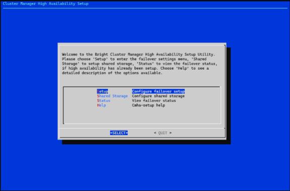
Figure 35 The cmha-setup main menu with the Setup option highlighted.#
Select Configure.
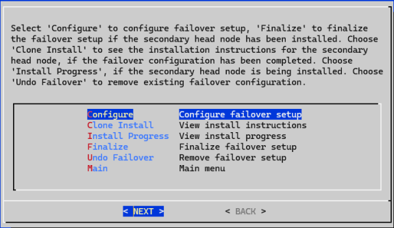
Figure 36 The cmha-setup Setup submenu with the Configure option highlighted.#
Select Continue.
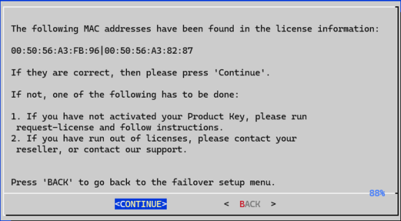
Figure 37 Dialog confirming the MAC addresses found in the license information, with the Continue option.#
Enter the HA shared interface name and IP address.
a. Name:
bond0:hab. IP:
192.168.100.254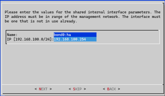
Figure 38 Dialog for entering the HA shared internal interface name and IP address.#
Enter the hostname of the secondary node.
a. Name:
nvidia-era-bcm-02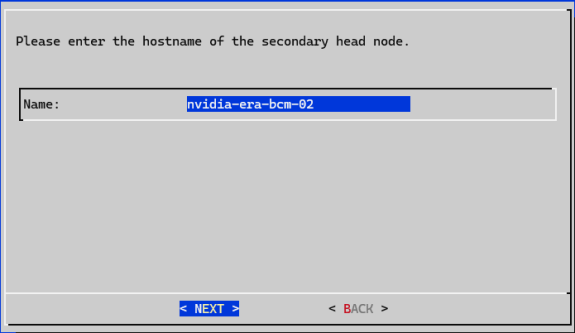
Figure 39 Dialog for entering the hostname of the secondary head node.#
Set the failover network.
a. Name:
failovernetb. Base address:
192.168.120.0c. Netmask:
255.255.255.0d. Domain name:
failover.cluster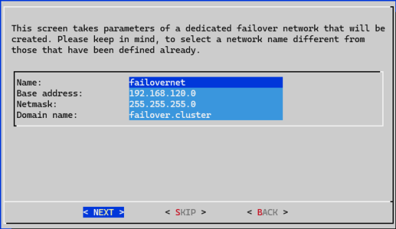
Figure 40 Dialog for entering the failover network name, base address, netmask, and domain name.#
Set the failover network interfaces.
a. Interface (primary):
eth0b. IP (primary):
192.168.120.11c. Interface (secondary):
eth0d. IP (secondary):
192.168.120.12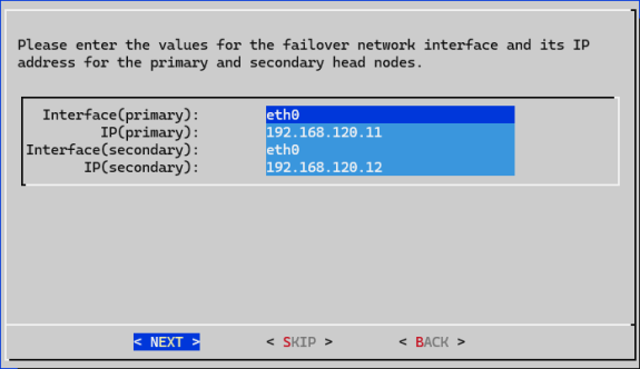
Figure 41 Dialog for entering the failover network interface and IP for the primary and secondary head nodes.#
Set the IP address for the secondary head node.
a. Secondary IP:
192.168.100.252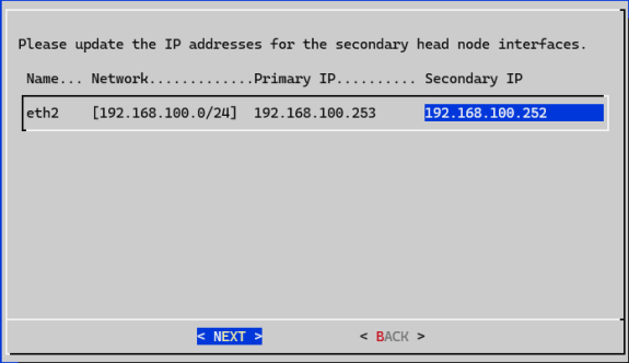
Figure 42 Dialog for updating the IP addresses for the secondary head node interfaces.#
Review the summary and select Exit.
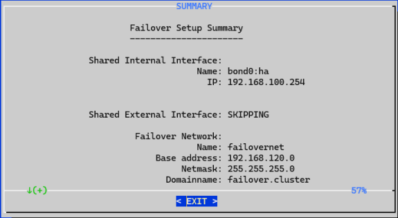
Figure 43 Summary screen showing all configured HA parameters.#
Select Yes to proceed.
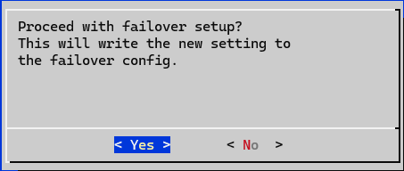
Figure 44 Confirmation dialog to proceed with the HA configuration.#
Enter the mysql root password.
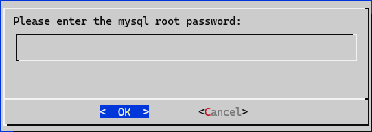
Figure 45 Dialog for entering the MySQL root password.#
Wait until all tasks are completed, then press Enter.
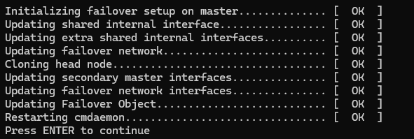
Figure 46 Progress screen showing all HA setup tasks completing.#
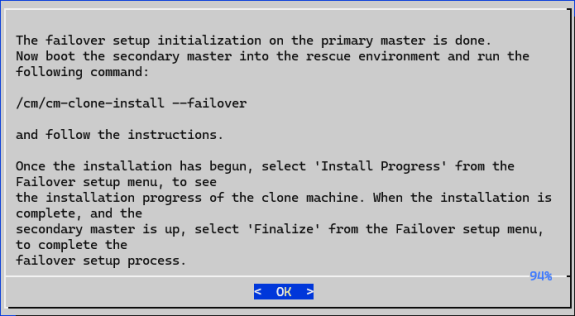
Figure 47 Dialog instructing to boot the secondary head node into the rescue environment and run the clone install command.#
Follow the Instructions on the Secondary Head Node#
The secondary head node can now be powered on, booted from network into the rescue environment, and cloned from the primary head node using the failover parameter. Note that the BCM ISO is not required for this process.
Power on and boot the secondary head node server from the network (PXE).
Select Start rescue environment.
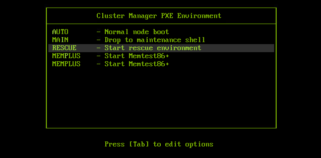
Figure 48 PXE boot menu with the Start rescue environment option highlighted.#
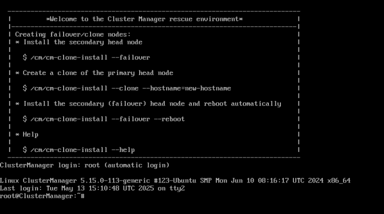
Figure 49 The rescue environment boot screen.#
Determine the network interface to use for configuration.
root@ClusterManager:~# ip a
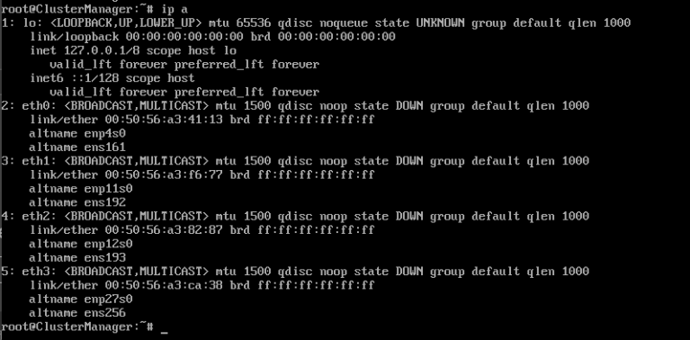
Figure 50 Output of the ip a command showing available network interfaces on the secondary head node.#
Clone install failover (non-interactive).
root@ClusterManager:~# /cm/cm-clone-install \
--failover \
--noninteract \
--headnodepasswd=secret \
--interface=eth2 \
--addbiosboot
Wait until all tasks are completed. The secondary head node will automatically reboot.
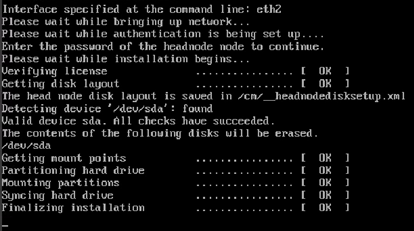
Figure 51 Output showing the clone install failover process completing and the secondary head node rebooting.#
Finalize cmha-setup on the Primary Head Node#
Back on the primary head node, the HA process must now be finalized.
From the cmha-setup > Setup TUI, select Finalize.
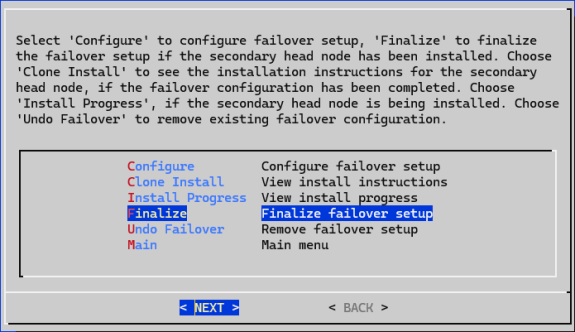
Figure 52 The cmha-setup Setup submenu with the Finalize option highlighted.#
Select Continue.
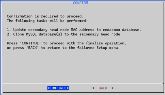
Figure 53 Confirmation dialog to continue with the finalization.#
Enter the mysql root password.
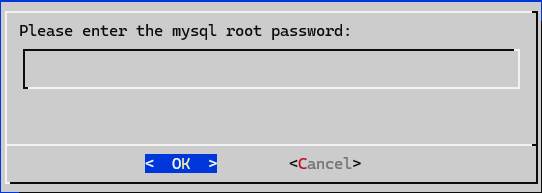
Figure 54 Dialog for entering the MySQL root password during finalization.#
Wait until all tasks are complete, then press Enter.
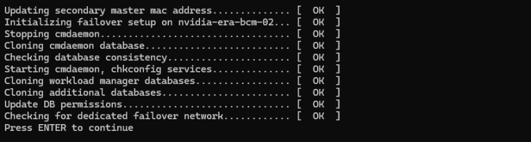
Figure 55 Progress screen showing all finalization tasks completing.#
Select Reboot to reboot the secondary head node.
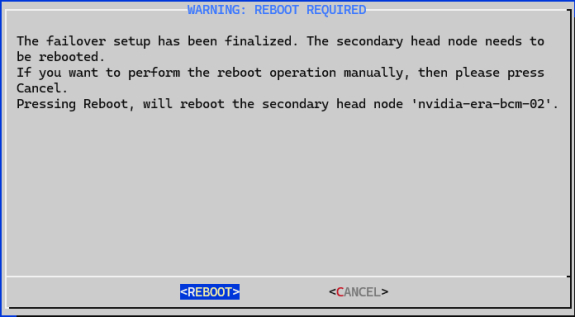
Figure 56 Dialog to reboot the secondary head node.#
Select Main.
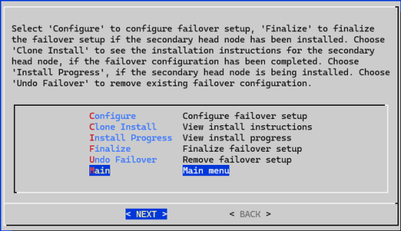
Figure 57 The cmha-setup main menu after finalization.#
Configure Shared Storage#
Shared storage can now be configured to use the home and cmshared directories from earlier.
In cmha-setup > TUI, select Shared Storage.
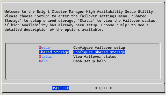
Figure 58 The cmha-setup main menu with the Shared Storage option highlighted.#
Select NAS.
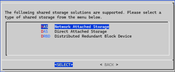
Figure 59 The Shared Storage submenu with the NAS option highlighted.#
Select the resources that will be shared:
a.
/homeb.
/cm/shared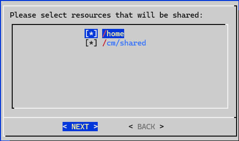
Figure 60 Dialog for selecting the resources to be shared via NAS.#
Enter the NAS parameters.
a. NAS host:
192.168.255.31b. Path to /home:
/nvidia-era-bcm-cluster/ha/homec. Path to /cm/shared:
/nvidia-era-bcm-cluster/ha/cmshared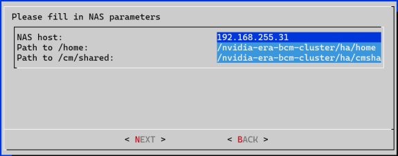
Figure 61 Dialog for entering the NAS host and path parameters.#
Review the summary and select Exit.
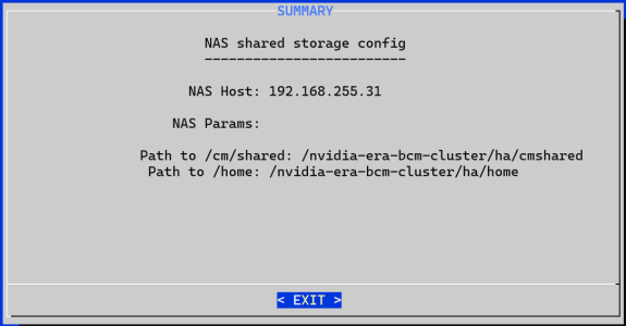
Figure 62 Summary screen showing the configured NAS shared storage parameters.#
Proceed with nas setup by selecting Yes.
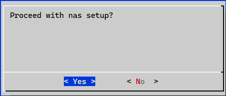
Figure 63 Confirmation dialog to proceed with the NAS setup.#
Wait for tasks to complete, then press Enter.

Figure 64 Progress screen showing the NAS shared storage setup tasks completing.#
Exit cmha-setup. Select Exit, then Quit, then Yes.
Test Failover and Reboot the Primary Head Node#
From this point forward, it is recommended to log in using the HA shared internal interface IP address defined during the HA setup (in this example, 192.168.100.254). This ensures that administrators are always directed to the active head node, which is currently still the primary head node.
In the event of a failover, this IP address will be assumed by the secondary head node, minimizing downtime and service disruption. To proceed, the primary head node will need a reboot. A failover will be simulated by making the secondary head node the active head node, allowing the primary head node to reboot gracefully.
Log off from the primary head node.
root@nvidia-era-bcm-01:~# exit
Log in using the HA shared internal interface IP address.
ssh root@192.168.100.254
Figure 65 Node status showing the session is connected to the active head node (nvidia-era-bcm-01).#
Note
The primary head node (nvidia-era-bcm-01) is still the active head node.
Enter cmsh.
root@nvidia-era-bcm-01:~# cmshCheck the failover status and make the secondary head node the active head node.
a. Enter the partition mode.
[nvidia-era-bcm-01]% partition
b. Enter the failover submenu.
[nvidia-era-bcm-01->partition[base]]% failover
c. Get the failover status.
[nvidia-era-bcm-01->partition[base]->failover]% status
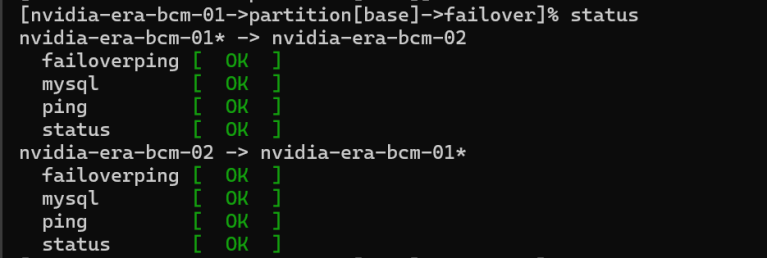
Figure 66 Output of the failover status command showing the primary head node as the active head node.#
d. Make the secondary head node active. (Pressing Enter after this command will disconnect the client.)
[nvidia-era-bcm-01->partition[base]->failover]% makeactive nvidia-era-bcm-02

Figure 67 The makeactive command for nvidia-era-bcm-02, after which the client connection is reset.#
Log in again using the HA shared internal interface IP address.
ssh root@192.168.100.254
Figure 68 Node status showing the session is now connected to the active head node (nvidia-era-bcm-02).#
Note
The secondary head node (nvidia-era-bcm-02) is now the active head node.
Enter cmsh again.
root@nvidia-era-bcm-02:~# cmshEnter the partition mode.
[nvidia-era-bcm-02]% partition
Enter the failover submenu.
[nvidia-era-bcm-02->partition[base]]% failover
Get the failover status.
[nvidia-era-bcm-02->partition[base]->failover]% status
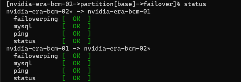
Figure 69 Output of the failover status command showing the secondary head node as the active head node.#
Reboot the primary head node.
a. Enter the device mode
[nvidia-era-bcm-02->partition[base]->failover]% device
b. List the devices.
[nvidia-era-bcm-02->device]% list

Figure 70 Output of the device list command showing the primary head node with a restart required.#
c. Reboot the primary head node.
[nvidia-era-bcm-02->device]% reboot nvidia-era-bcm-01

Figure 71 Output showing the reboot in progress for nvidia-era-bcm-01.#
d. Wait for the primary head node to come back up, then list the devices to verify status.
[nvidia-era-bcm-02->device]% list

Figure 72 Output of the device list command showing both head nodes up after the reboot.#
Make the primary head node is the active head node again.
a. Enter the partition mode.
[nvidia-era-bcm-02->device]% partition
b. Enter the failover submenu.
[nvidia-era-bcm-02->partition[base]]% failover
c. Make the primary head node active. (Pressing Enter after this command will show that the client is disconnected.)
[nvidia-era-bcm-02->partition[base]->failover]% makeactive nvidia-era-bcm-01

Figure 73 The makeactive command for nvidia-era-bcm-01, after which the client connection is reset.#
Log in again using the HA shared internal interface IP address.
ssh root@192.168.100.254