

Create Devices (Nodes)#
In this section, a device (node) will be created to represent a physical node in the cluster. While devices can be created from scratch using the add command, cloning the previously created template-default-node will copy the settings already applied (such as interfaces).
At this stage, it is likely unclear which interfaces on the physical node (as enumerated by the operating system) correspond to the DPU interfaces on the N-S internal network that form the logical bond interface.
To determine this, the node will first be brought up using the default category (which uses the default-image software image) and the BCM special interface BOOTIF. From within the operating system, the network interfaces will be listed to identify which of the interfaces correspond to the DPU interfaces.
In BCM, the node object interfaces will then be updated by adding the two physical interfaces and the bond interface.
After this, the node category will be changed to the custom category (which uses the custom-image software image).
In a homogeneous environment, where all nodes are identical, it can be assumed that the OS will enumerate the interfaces in the same way. In this case, the newly created node can be used as a template to clone additional nodes.
In a heterogeneous environment, these preliminary and subsequent steps may need to be repeated for each group of similar node types.
Note
Example values displayed in red should be replaced with actual information relevant to the target environment.
Create the device.
a. Enter cmsh.
root@nvidia-era-bcm-01:~# cmshb. Enter the device mode.
[nvidia-era-bcm-01]% device
c. List the current devices.
[nvidia-era-bcm-01->device]% list

Figure 91 Output of the list command showing the current devices, including template-default-node.#
d. Clone template-default-node to oem-node001.
[nvidia-era-bcm-01->device]% clone template-default-node oem-node001 --next-ip
e. Set the category to default.
[nvidia-era-bcm-01->device*[oem-node001*]]% set category default
f. Commit the changes.
[nvidia-era-bcm-01->device*[oem-node001*]]% commit
g. Exit to return to device mode and list the devices to confirm creation.
[nvidia-era-bcm-01->device[oem-node001]]% exit
[nvidia-era-bcm-01->device]% list

Figure 92 Output of the list command confirming the newly created oem-node001 device.#
Preliminary. Bring up the node.
Note
Instructions will vary by OEM. Refer to the manufacturer’s documentation for detailed instructions.
a. Power on and boot the node from the network (PXE).
b. Allow the node to boot to AUTO.
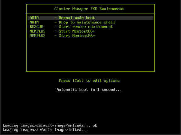
Figure 93 PXE boot menu with AUTO (normal node boot) selected.#
c. When prompted as an unknown node, the Cluster Manager Node Installer will loop. Select Manually select node.
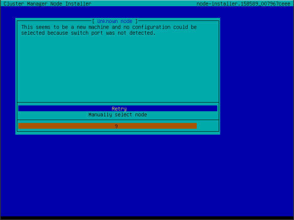
Figure 94 Cluster Manager Node Installer prompt for an unknown node, showing the option to manually select a node.#
d. Select the newly created node.
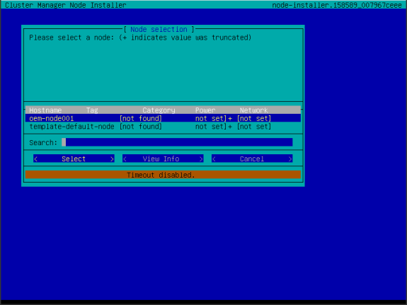
Figure 95 Node selection screen showing the newly created oem-node001.#
e. Accept the selection.
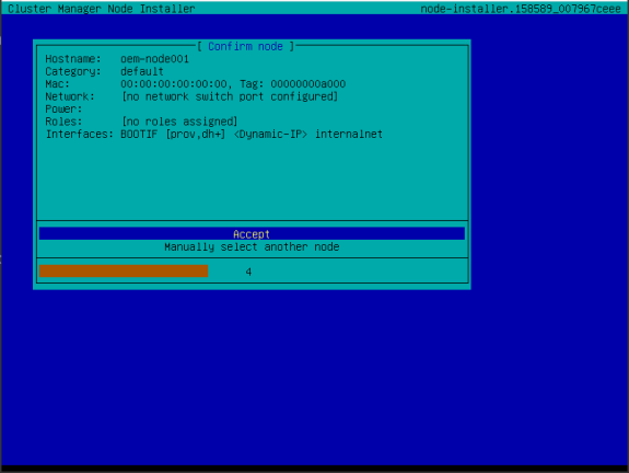
Figure 96 Confirm node screen for oem-node001 with the Accept option.#
f. Wait until the node is fully booted.
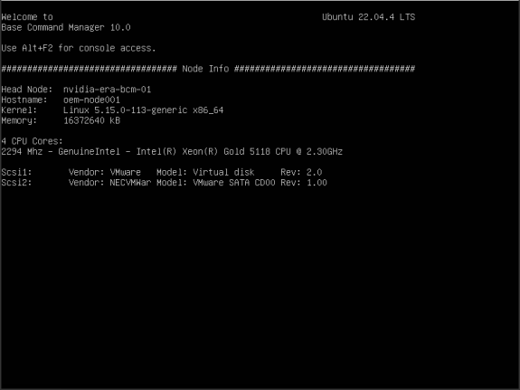
Figure 97 The node fully booted, showing the Base Command Manager node info screen.#
From cmsh on the head node, log in to the new node using the rshell (remote shell) command.
a. Enter cmsh.
root@nvidia-era-bcm-01:~# cmshb. Enter the device mode.
[nvidia-era-bcm-01]% device
c. Use the node previously created.
[nvidia-era-bcm-01->device]% use oem-node001
d. Use the command rshell to connect to the node.
[nvidia-era-bcm-01->device[oem-node001]]% rshell

Figure 98 The rshell session connected to oem-node001.#
On the new node, identify the interfaces and IP addresses.
a. Run the command ip a.
root@oem-node001:~# ip a
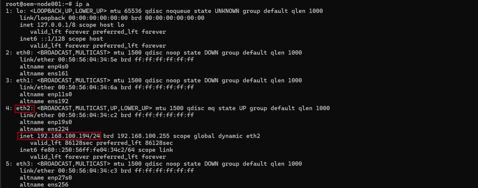
Figure 99 Output of ip a showing eth2 with an IP address in the 192.168.100.0/24 range.#
Note
In this example, eth2 has an IP address in the internal network range (192.168.100.0/24), and is therefore presumed to be the first DPU interface. It is logical that the next interface. eth3 is the second DPU interface. This can be confirmed in the next steps. If no interface has an IP address in this range, the server’s boot device may not be configured to be the first interface of the DPU. Adjust the server’s PXE boot order and repeat the procedure. Instructions will vary by OEM and are not covered in this guide.
Note
The interfaces shown in this example may differ from the target environment, depending on the chosen cluster architecture and OEM. For example, with the additional network interfaces in compute nodes, the DPU interfaces could very well be enumerated as eth7 and eth8, or eth10 and eth11. It is important to identify the correct interfaces at this stage.
b. Run the command dhclient to bring up any inactive interfaces that are down.
root@oem-node001:~# dhclient
Figure 100 Output of the dhclient command.#
c. Run the command ip a again.
root@oem-node001:~# ip a
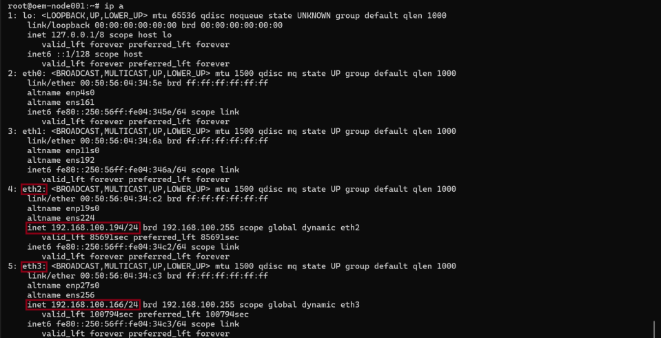
Figure 101 Output of ip a showing both DPU interfaces eth2 and eth3 with IP addresses in the 192.168.100.0/24 range#
Note
At this stage, both eth2 and eth3 should have IPs in 192.168.100.0/24, confirming they are DPU interfaces. If not, further investigation is required.
d. Exit rshell to return to the head node.
root@oem-node001:~# exit

Figure 102 Exiting the rshell session to return to the head node.#
While still in the context of device -> oem-node001, set the category to custom, which in turn will apply the custom-image software image when the node is rebooted.
[nvidia-era-bcm-01->device[oem-node001]]% set category custom
Modify the nodes interfaces to add the physical interfaces and the bond interface.
a. Enter the interfaces submenu.
[nvidia-era-bcm-01->device[oem-node001]]% interfaces
b. List the interfaces.
[nvidia-era-bcm-01->device[oem-node001]->interfaces]% list

Figure 103 Output of the list command showing the current interfaces for oem-node001#
c. Remove the BOOTIF interface.
[nvidia-era-bcm-01->device[oem-node001]->interfaces]% remove bootif
d. Add the physical interface eth2 and exit.
[nvidia-era-bcm-01->device*[oem-node001*]->interfaces*]% add physical eth2
[nvidia-era-bcm-01->device*[oem-node001*]->interfaces*[eth2*]]% exit
e. Add the physical interface eth3 and exit.
[nvidia-era-bcm-01->device*[oem-node001*]->interfaces*]% add physical eth3
[nvidia-era-bcm-01->device*[oem-node001*]->interfaces*[eth3*]]% exit
f. Add the bonded interface bond0.
[nvidia-era-bcm-01->device*[oem-node001*]->interfaces*]% add bond bond0
g. Set DHCP on bond0.
[nvidia-era-bcm-01->device*[oem-node001*]->interfaces*[bond0*]]% set dhcp yes
h. Clear the current IP address.
[nvidia-era-bcm-01->device*[oem-node001*]->interfaces*[bond0*]]% clear ip
i. Set the network to internalnet.
[nvidia-era-bcm-01->device*[oem-node001*]->interfaces*[bond0*]]% set network internalnet
j. Set the bond interfaces to eth2 and eth3.
[nvidia-era-bcm-01->device*[oem-node001*]->interfaces*[bond0*]]% set interfaces eth2 eth3
k. Set the bond mode to 4 (LACP).
[nvidia-era-bcm-01->device*[oem-node001*]->interfaces*[bond0*]]% set mode 4
l. Set the options to miimon=100 and xmit_hash_policy=layer3+4.
[nvidia-era-bcm-01->device*[oem-node001*]->interfaces*[bond0*]]% set options "miimon=100 xmit_hash_policy=layer3+4"
m. Exit to the interfaces submenu.
[nvidia-era-bcm-01->device*[oem-node001*]->interfaces*[bond0*]]% exit
n. List the interfaces.
[nvidia-era-bcm-01->device*[oem-node001*]->interfaces*]% list

Figure 104 Output of the list command showing all configured interfaces including eth2, eth3, and bond0#
o. Exit to the device submenu.
[nvidia-era-bcm-01->device*[oem-node001*]->interfaces*]% exit
p. Set the provisioning interface to bond0.
[nvidia-era-bcm-01->device*[oem-node001*]]% set provisioninginterface bond0
q. Commit the changes.
[nvidia-era-bcm-01->device*[oem-node001*]]% commit
r. Reboot the node.
[nvidia-era-bcm-01->device[oem-node001]]% reboot
At this point, the node should come back up with the bond interface active.
a. Connect to the node again.
[nvidia-era-bcm-01->device[oem-node001]]% rshell
b. Run command ip a.
root@oem-node001:~# ip a
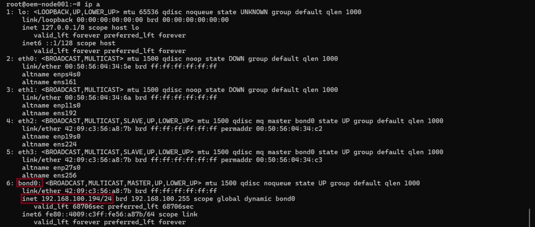
Figure 105 Output of ip a showing the bond0 interface is up and active#
Note
Notice that the bond0 interface is up.
c. Exit the remote shell.
root@oem-node001:~# exit
Once verified, this node configuration can be cloned to create additional nodes with the same bonded interface setup. For example, 2 additional nodes can be created by using the following commands:
[nvidia-era-bcm-01->device]% clone oem-node001 oem-node002 --next-ip
[nvidia-era-bcm-01->device*[oem-node002*]]% exit
[nvidia-era-bcm-01->device*]% clone oem-node001 oem-node003 --next-ip
[nvidia-era-bcm-01->device*[oem-node003*]]% exit
[nvidia-era-bcm-01->device*]% commit
[nvidia-era-bcm-01->device]% list

Figure 106 Output of the list command showing the additional cloned nodes oem-node002 and oem-node003.#
For nodes with different configurations (for example, in a heterogenous cluster with nodes of differing models or from different manufacturers) the entire section should be repeated until all nodes are configured. (i.e. clone the template-default node, identify and configure the interfaces, set the applicable category, clone again.)