

Installation#
This section describes the minimal settings required to install NVIDIA Base Command Manager on the primary head node. While the options selected here should be customized to suit the target environment during installation, many settings can also be reconfigured post install.
For more detailed information, please refer to the installation manual.
Details required to complete this section, with example values used in this guide:
Setting |
Example Value |
|---|---|
Cluster Name |
nvidia-era-bcm-cluster |
Organization Name |
NVIDIA |
Time zone |
(GMT-07:00) America/Los_Angeles |
Name servers |
192.168.255.25, 192.168.255.26 |
Search domains |
nvidia.com |
Hostname |
nvidia-era-bcm-01 |
Base IP address |
192.168.100.0 |
Netmask |
255.255.255.0(/24) |
Dynamic range start |
192.168.100.101 |
Dynamic range end |
192.168.100.250 |
Gateway |
192.168.100.1 |
Head node interface |
ens224 |
IP address |
192.168.100.253 |
IP offset |
0.0.0.20 |
Installation drives |
/dev/nvme0n1 |
Note
Where applicable these values will be displayed in red. Be sure to replace all example values with actual information relevant to the target environment.
Power on and boot the primary head node server from the installation ISO.
Select Start Base Command Manager Graphical Installer.
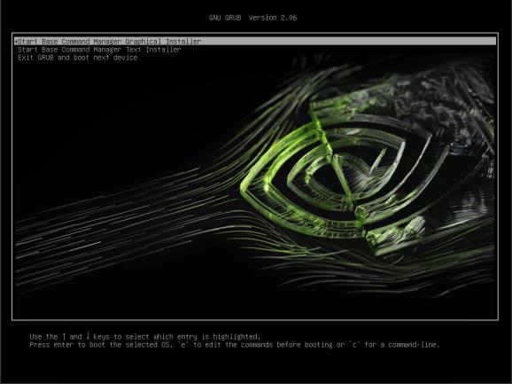
Figure 2 GRUB boot menu with Start Base Command Manager Graphical Installer selected#
Welcome Screen.
a. Select Start Installation.
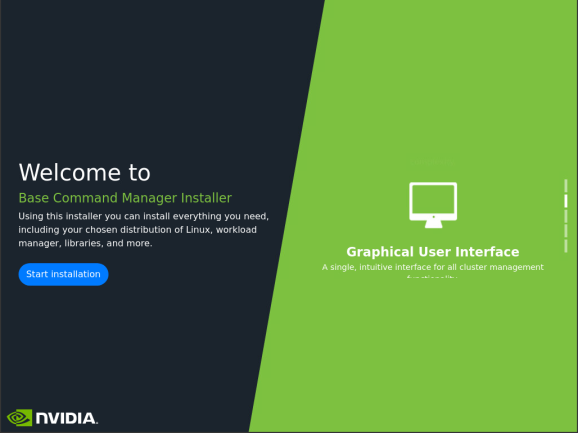
Figure 3 Welcome screen with the Start Installation button#
Software Licenses. NVIDIA EULA.
a. Check the I agree checkbox.
b. Click Next to continue.
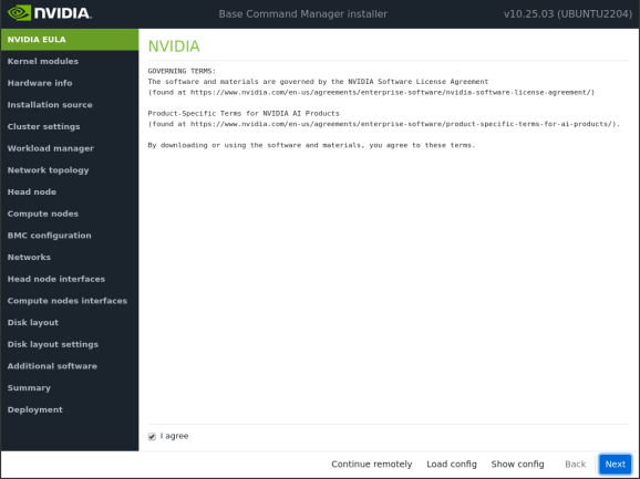
Figure 4 NVIDIA EULA software license agreement screen#
Software License. Ubuntu Server EULA.
a. Check the I agree checkbox.
b. Click Next to continue.
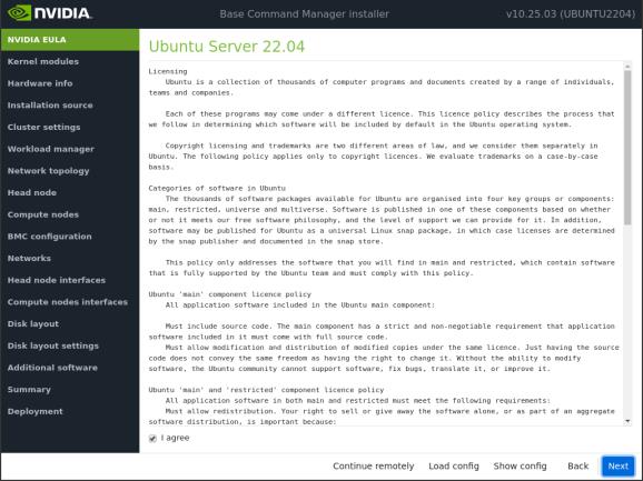
Figure 5 Ubuntu Server EULA software license agreement screen#
Kernel Modules Configuration.
a. Click Next to continue.
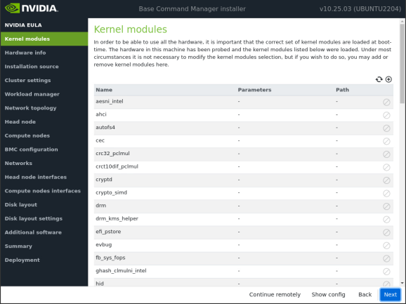
Figure 6 Kernel Modules Configuration screen#
Note
The Kernel Modules screen displays the modules recommended for loading based on a hardware probe. In most cases, the default selections can be accepted without adding additional modules.
Hardware Info.
a. Click Next to continue.
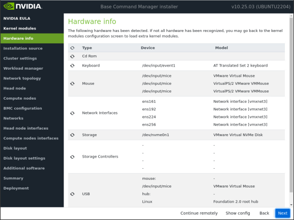
Figure 7 Hardware Info screen showing detected hardware#
Note
The Hardware Info screen provides an overview of detected hardware based on the hardware probe used to load kernel modules. If any hardware is not detected at this stage, use the Back button to return to the Kernel Modules screen, add the appropriate modules, and then revisit the Hardware Info screen to verify detection.
Installation Source.
a. Select the installation media from the list.
b. Click Next to continue.
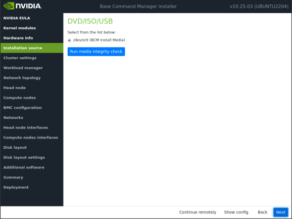
Figure 8 Installation Source screen showing available installation media#
Cluster Settings.
a. Enter information for the target environment:
i. Cluster name:
nvidia-era-bcm-clusterii. Organization name:
NVIDIAiii. Time zone:
(GMT-07:00) America/Los_Angelesiv. Name servers:
192.168.255.25 192.168.255.26v. Search domains:
nvidia.comb. Click Next to continue.
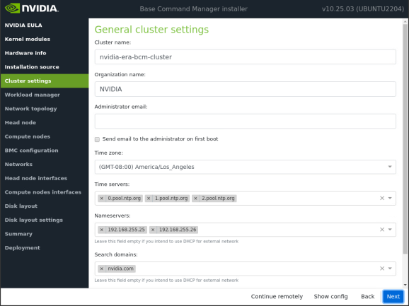
Figure 9 Cluster Settings screen with cluster name, organization, time zone, name servers, and search domains#
Workload Management Configuration.
a. Select None.
b. Click Next to continue.
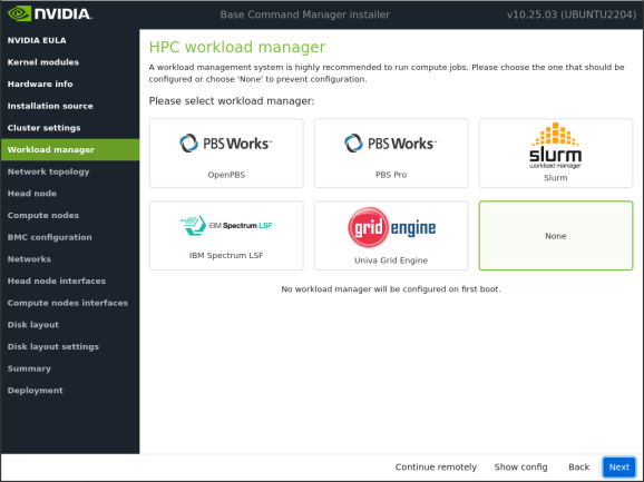
Figure 10 Workload Management Configuration screen with None selected#
Note
If no workload manager is selected here, one can be installed later after completing the cluster installation without it. Instructions for installing a workload manager post-installation are provided in the BCM Administrator Manual.
Network Topology.
a. Select Type 2.
b. Click Next to continue.
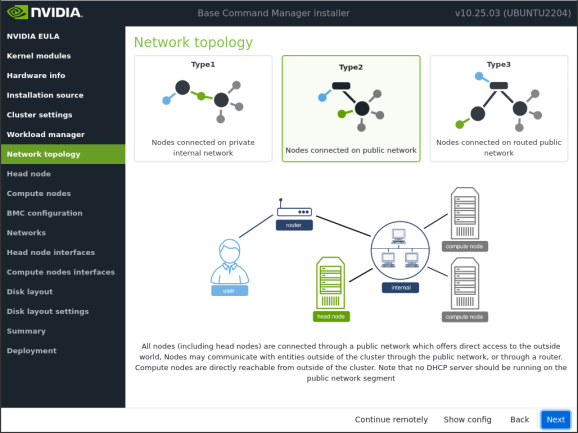
Figure 11 Network Topology screen with Type 2 selected#
Note
The design provided is based on the deployment of a type 2 network - a type 2 network has the compute nodes connected via a router to a public network.
For more information on the different network topologies supported by BCM, please refer to the BCM Administrator Manual.
Head node Settings.
a. Enter the following information:
i. Hostname:
nvidia-era-bcm-01ii. Password:
<Password>b. Click Next to continue.
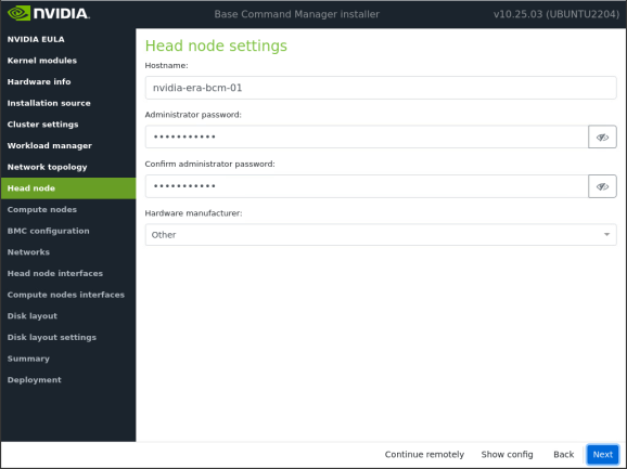
Figure 12 Head node Settings screen with hostname and password fields#
Compute Nodes Settings.
a. Accept the default settings.
b. Click Next to continue.
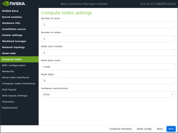
Figure 13 Compute Nodes Settings screen with default settings#
BMC Configuration.
a. Accept the default settings.
b. Click Next to continue.
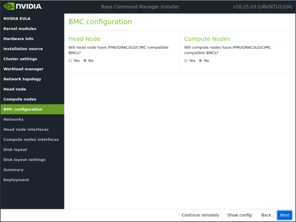
Figure 14 BMC Configuration screen with default settings#
Networks.
a. Ensure Internalnet is selected.
b. Enter the following information:
i. Base IP address:
192.168.100.0ii. Netmask:
255.255.255.0(/24)iii. Dynamic range start:
192.168.100.101iv. Dynamic range end:
192.168.100.250v. Gateway:
192.168.100.1c. Click Next to proceed.
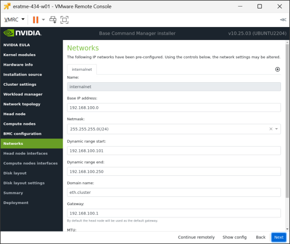
Figure 15 Networks screen showing Internalnet configuration with IP address range settings#
Note
As per the NVIDIA Enterprise Reference Architecture, the first 20 IP addresses are reserved for network services.
Setting the dynamic range start and end values suggested allows for other “static” or “reserved” IP addresses to be used in the range 192.168.100.21-192.168.100.100.
The compute nodes utilize the DHCP assigned range 192.168.100.101-192.168.100.250.
The BCM head nodes and High Availability shared IP address use the range 192.168.100.251-192.168.100-254.
Head node Interfaces.
a. Select the appropriate interface.
Note
This should be set to the first interface of the DPU. In this example, the interface is listed as ens224, but in the target environment it should be enumerated in a pattern similar to enpXXs0f0np0.
b. Set the IP address:
192.168.100.253Note
It is suggested: use at least -1 from the last address in the usable range to allow for High Availability. For example: 192.168.100.253.
c. Click Next to continue.
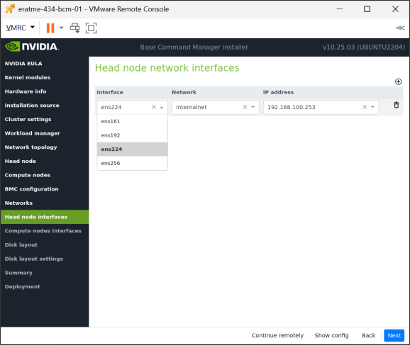
Figure 16 Head node Interfaces screen showing interface selection and IP address configuration#
Compute node interfaces.
a. Set the IP offset:
0.0.0.20b. Click Next to continue.
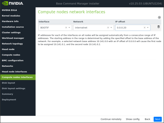
Figure 17 Compute node interfaces screen with IP offset set to 0.0.0.20#
Note
Setting the IP offset to 0.0.0.20 configures the IP address of the first compute node to 192.168.100.21. Later in this guide, this will be changed to use a DHCP assigned IP address.
Disk Layout.
a. Select the appropriate installation drives:
/dev/nvme0n1Note
In this example, there is only one drive listed, but in the target environment there may be multiple. It is recommended to select the hardware RAID configured disk.
b. Click Next to proceed.
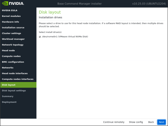
Figure 18 Disk Layout screen showing available installation drives#
Disk Layout Settings.
a. Head node disk layout:
i. Select One big partition. This setting cannot be not easily changed after installation.
b. Compute node disk layout:
i. Select One big partition. This will be further configured after installation.
c. Click Next to continue.
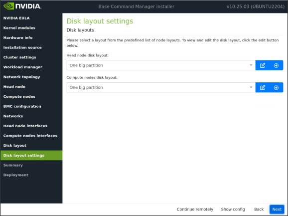
Figure 19 Disk Layout Settings screen with One big partition selected for both head node and compute node#
Summary.
a. Review all configuration settings to ensure they are correct.
b. Click Start to begin the installation.
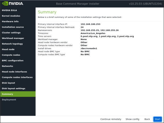
Figure 20 Summary screen showing all configuration settings before installation begins#
Deployment.
a. Check the Automatically reboot after installation is complete checkbox.
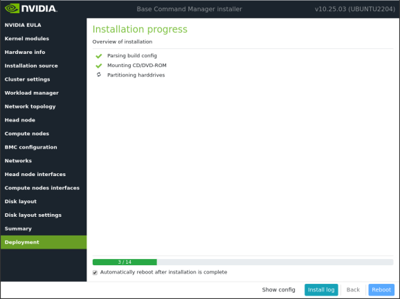
Figure 21 Deployment screen showing installation progress with automatic reboot option#