Hardware Layout#
The Jetson Orin Nano Developer Kit includes a Jetson Orin Nano module with a microSD card slot and a reference carrier board for development and prototyping.
Developer Kit#
Side Views#
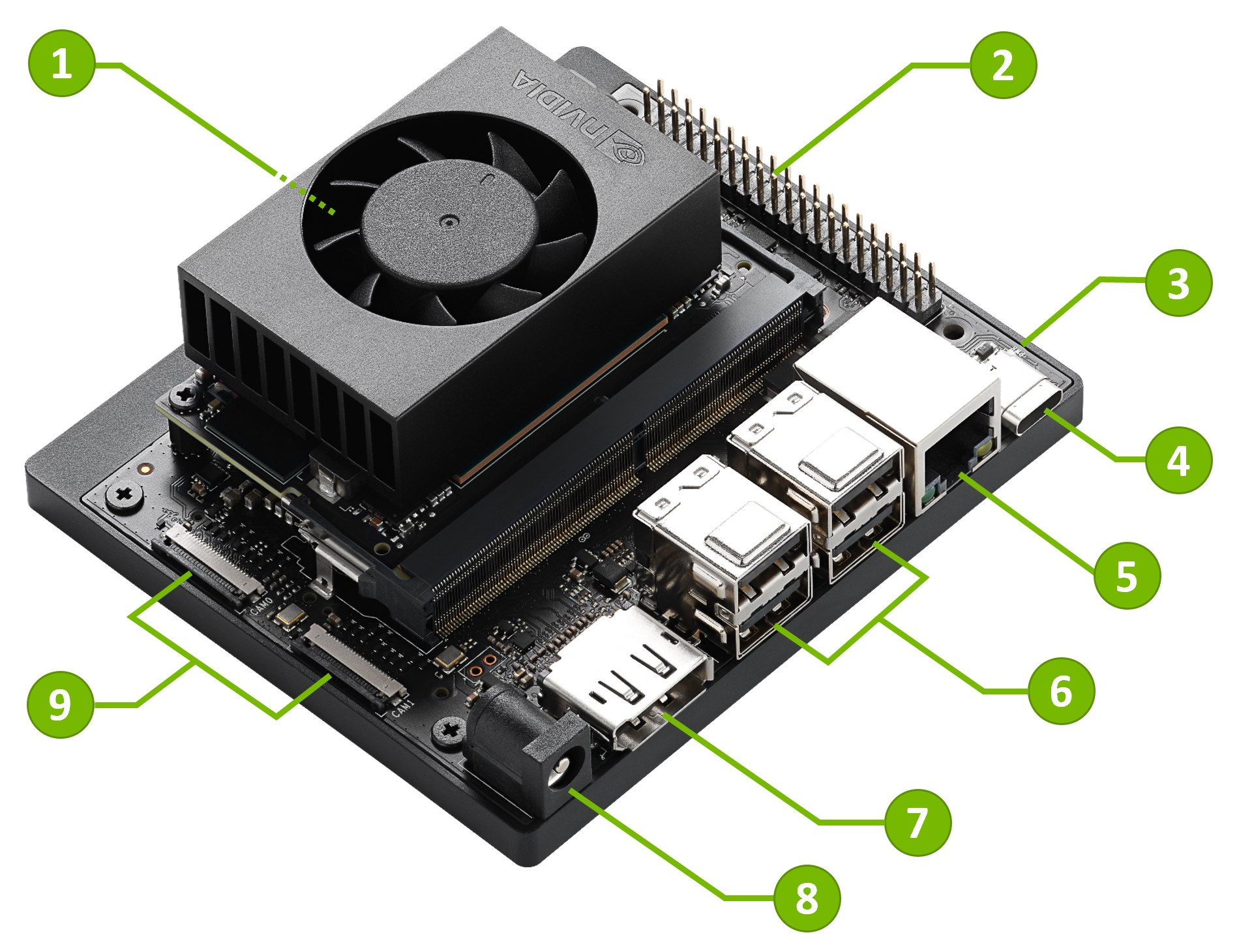
Part Names#
Mark. |
Name |
Note |
|---|---|---|
1 |
microSD card slot |
Main storage on the Jetson Orin Nano module |
2 |
40-pin Expansion Header |
|
3 |
Power indicator LED |
|
4 |
USB-C port |
For data only |
5 |
Gigabit Ethernet port |
|
6 |
USB 3.2 Type-A ports (x4) |
10Gbps |
7 |
DisplayPort output connector |
|
8 |
DC power jack |
5.5mm x 2.5mm |
9 |
MIPI CSI camera connectors (x2) |
22-pin, 0.5mm pitch |
10 |
M.2 slot (Key-M, Type 2280) |
PCIe 3.0 x4 |
11 |
M.2 slot (Key-M, Type 2230) |
PCIe 3.0 x2 |
12 |
M.2 slot (Key-E, Type 2230) |
Populated with the included wireless module |
Port and Connector Details#
Note
For electrical details, pin assignments, and design constraints, see the Jetson Orin Nano Developer Kit Carrier Board Specification from the Jetson Download Center.
Storage#
Default storage:
microSD card on the Jetson Orin Nano module (mark 1)
Optional storage:
2280-size NVMe SSD on the M.2 Key-M Type 2280 slot (mark 10)
2230-size NVMe SSD on the M.2 Key-M Type 2230 slot (mark 11)
USB drive connected to the USB-C port (mark 4) or USB Type-A ports (mark 6)
You can flash the base Jetson Linux BSP to supported storage media with NVIDIA SDK Manager. See BSP Setup for setup options.
USB Ports#
USB-C port (mark 4)#
The USB 3.2 Type-C connector supports Host mode, Device mode, and USB Recovery mode.
Attention
The USB-C port does not output a display signal. HDMI or DisplayPort over USB-C are not supported.
- Host mode
Use this port as a downstream-facing port, similar to the USB Type-A ports. You can connect supported USB devices and use Jetson as the host.
- Device mode
Connect the developer kit to a PC with a USB-C to USB-A or USB-C to USB-C cable and have Jetson act as a USB device.
USB Device Mode exposes these logical USB devices:
USB Mass Storage device for the
L4T-READMEdriveUSB Serial device for serial terminal access
USB Ethernet (RNDIS) device for a local network between the PC and Jetson, with Jetson at
192.168.55.1
- USB Recovery mode
When the developer kit is in Force Recovery Mode, this connector operates in USB Recovery mode. Connect it to a host PC to flash Jetson.
USB 3.2 Type-A ports (mark 6)#
Use the four USB Type-A ports to connect USB devices. These ports are host mode only.
There are two dual-stacked Type-A connectors. Each stack has VBUS limited to 3A output current.
DisplayPort Output#
Use the DisplayPort output connector (mark 7) to connect a display to the developer kit.
This is the only display output on Jetson Orin Nano Developer Kit. HDMI output and DisplayPort over USB-C are not supported.
To connect a monitor or TV that only accepts HDMI, use a DisplayPort-to-HDMI adapter or cable. The DisplayPort output supports both passive and active DisplayPort-to-HDMI adapters.
40-pin Expansion Header#
The 40-pin expansion header (mark 2) provides GPIO and peripheral interfaces for development and prototyping.
For pin assignments, voltage levels, and electrical limits, see the Jetson Orin Nano Developer Kit Carrier Board Specification from the Jetson Download Center.
MIPI CSI Camera Connectors#
The carrier board includes two 22-position flex connectors for CSI camera modules.
To connect a CSI camera module with a 15-pin connector, such as Raspberry Pi Camera Module v2, use a 15-pin to 22-pin conversion cable.
The connectors support:
CAM0: CSI 1 x2 laneCAM1: CSI 1 x2 lane or 1 x4 lane
The camera connectors are bottom-contact, 0.5mm pitch, 22-position connectors.