Cable Installation and Management Guidelines
Unpacking of cables and transceivers should be done in an environment which complies with the storage humidly specified in the product datasheet. Cables and transceivers contain active electronic components. i.e. the products are designed with sufficient ESD tolerance to make them fit for use in datacenters. Please refer to the product datasheet of each cable/transceiver for specific ESD information and observe standard ESD precautions when unpacking and plugging the cables/transceivers into the host systems.
This section is based on experience from damages found on cables returned to Nvidia, which in most cases cannot be repaired.
Do not twist the cables.
Do not pull the cables.
Do not staple the cables.
Do not uncoil the cable, as a kink might occur.
Do not step on the cable or connectors. Plan cable paths away from foot traffic or rolling loads.
Do not pull the cable out of the shipping box through any opening or around any corners. Unroll the cable as you lay it down and move it through turns.
Do not open a kink by twisting the cable. If it is not severe, open the kink by unlooping the cable.
Do not pack the cable to fit a tight space. Use an alternative cable route.
Do not hang the cable for a length of more than 2 meters (7 feet). Minimize the hanging weight with intermediate retention points.
Do not drop the cable or connectors from any height. Gently set the cable down, resting the cable connectors on a stable surface.
Do not cinch or fix the cable with hard fasteners or cable ties. Use soft hook-and-loop fasteners or Velcro ties for bundling and securing cables.
Do not drag the cable or its connectors over any surface. Carry the entire cable to and from the points of connection.
Do not force the cable connector into the receptacle by pushing the cable. Apply connection or disconnection forces at the connector only.
Avoid over-bundling the cables or placing multiple bundles on top of each other. This can degrade the performance of the cables underneath.
Do not bend the cable beyond its recommended radius. Ensure that cable turns are as wide as possible.
Extreme Bend Radius
Strain on the Connector

CAUTION: Do not kink cables.

CAUTION: Do not bend cables beyond the recommended minimum radius.

CAUTION: Do not pull cables without using the proper pulling equipment to eliminate strain on the cable or connector.

CAUTION: Do not twist the cables.

CAUTION: Do not step, stand or roll equipment over the cables.

CAUTION: Do not lay cables on the floor.

CAUTION: Do not pull cables without using the proper pulling equipment to eliminate strain on the cable or connector.
Deformed Optical Cable
Do not Kink Cables while Packing and Unpacking
Small impurities like dirt and dust can destroy fiber optics. Airborne particles are about the size of the core of a single-mode fiber. They dampen the signal and may scratch the connectors if not removed.
CAUTION: Dirt is the most common cause of scratches on polished cable connectors and high loss measurements.
Work in a clean area. Avoid working around heating outlets, as they may blow dust on the optical connectors.
Always keep dust caps on connectors, bulkhead splices, patch panels or any other connection inlets.
Avoid exposing cables to direct sunlight and areas of condensation.
Remove unused cables which can restrict air flow. This is to prevent overheating.
Avoid placing copper cables near equipment that may generate high levels of electromagnetic interference, e.g. power converters or air conditioners.
Avoid running electrical cables near power cords, fluorescent lights, building electrical cables, and fire prevention components.
For the cable installation best practices within the rack, make sure of the following:
Ample space and easy access to replace any transceiver and system units (e.g. fan units) in the switch.
The rack is wide enough to place the cables between the switch and the rack's side walls.
The cables do not block air flow.
The cables do not block transceivers or system unit extraction.
The cables are tied to the rack structure to remove strain and tension on the connectors.
The weight of the cables is supported by the cable management system and the rack floor.
Provide strain relief on the cable. Support the cables every 2 meters or place cables in a tray.
Do not place cables and bundles where they may block other equipment.
Avoid routing cables through pipes and holes, as this may limit additional future cable runs.
Use Velcro based ties every 12” (30cm) to 24” (60cm).
Mount the cables to the rack, one by one, before plugging them into the switch to ensure optimal use of space. Use velcros in the process to eliminate weight burden.
Plug the cables in from the sides towards the middle. Bundle each half with velcros, then place the left half to the left side of the rack, and right half to the right side of the rack.
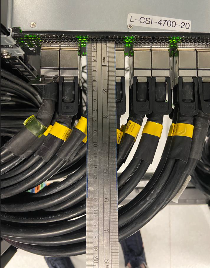
Pre-bend the cable tips before plugging them into the switch. This will significantly reduce the strain on the port, especially thicker cables, such as 26 AWG copper cables.
NVIDIA switch railkit allows recessing the switch deeper into the rack to minimize cable protrusion. The rack depth and air escape must be considered in this type of setup.
Test every cable as it is installed. Connect both ends and make sure that it has a physical and logical link before connecting the next cable.
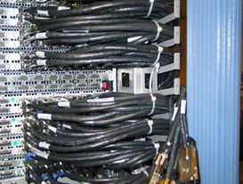
Correct Installation Examples
Plan for Leaf Extraction
Multi-mode fibers come in two dimensions, 50 and 62.5 µm core diameter. Do not mix 50 µm cables with 62.5 µm cables in the same link.
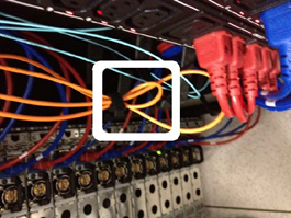
To ease management and troubleshooting, bundle cables together in groups of relevance (for example, ISL (Inter-Switch Link) cables and uplinks to core devices).
Use cables of correct length. Leave only a little slack at each end. Keep cable runs under 90% of the max distance supported for each media type, as specified in the applicable standard.
Keep copper and fiber runs separated.
Install spare cables in advance for future replacement of damaged cables.
Use color coding of the cable ties. The colors should indicate the endpoints. Place labels at both ends, as well as along the run.
Locate the main cabling distribution area in the middle of the data center.
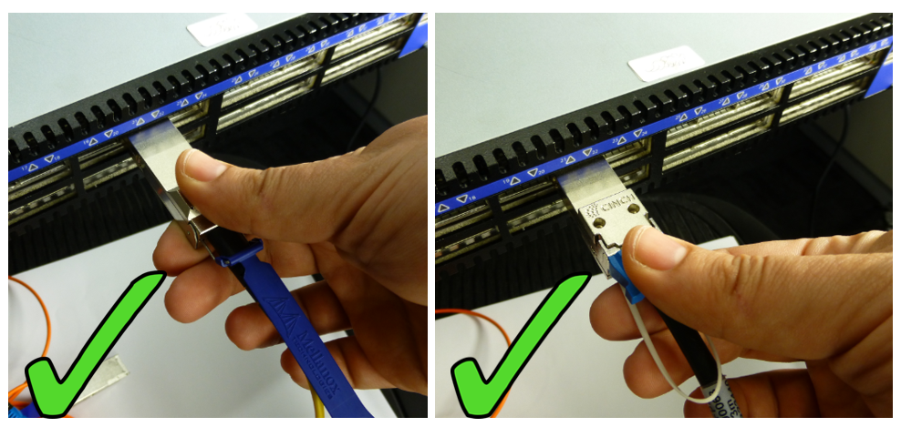
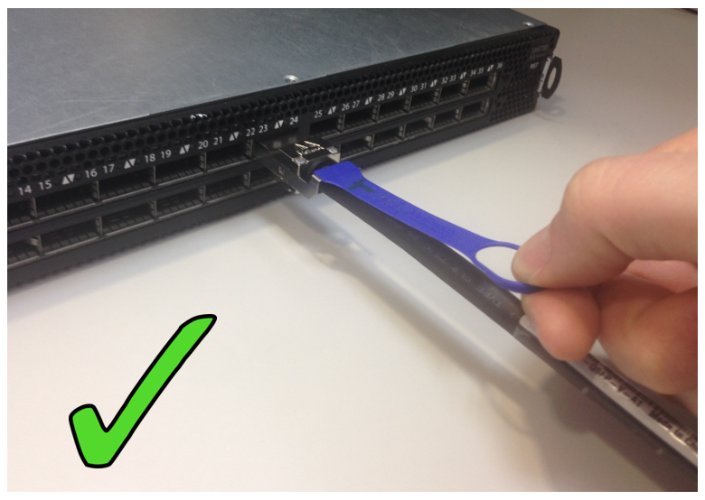
Please follow the instructions below to ensure smooth cable insertion and to avoid damage to the connector or target port.
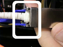
Grasp the cable by the lower part of the connector between your thumb and index finger. See figure below
Hold the cable connector perpendicularly to the ports panel, and gently push the connector into the port cage
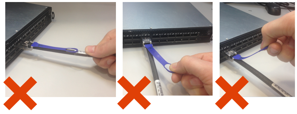
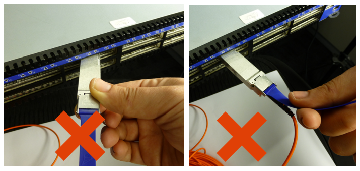
Do not hold or use the pull-tab to insert the cable. The pull-tab is intended for cable extraction only.
Insert Connector Perpendicularly to Panel
Incorrect Insertion
For a transceiver with integrated cable and pulltab, perform the following steps:
Grasp the pulltab and pull it firmly, but gently outwards perpendicularly to the panel’s face, until the transceiver is released from the panel’s port cage
Slide the transceiver and cable from the port
Do not grasp the cable’s jacket for extraction. Use the pulltab as shown in the figure.
Extract Pulltab Perpendicularly to Panel
Incorrect Extraction