Frequently Asked Questions (FAQ)
Q: Is there any difference between electrical cables and optical cables and transceivers that I should be aware of when using the latter?
A: Optical cables offer a much longer reach for transmission of high-speed data. For AOCs the optical interface is not accessible, and the installation of the AOC is the same as for an electrical cable.
For optimal performance of EDR (25 Gb/s SFP28/100 Gb/s QSFP28) cables and transceivers, it is imperative to optimize the optical transmitter’s input equalizer and the optical receiver output pre-emphasis to the host system (server, switch) characteristics. This is normally done by the host system in accordance with the MSA recommendation in SFF-8636. Alternatively, the AOC/transceiver can be specifically programmed to match the actual host system.
Optical links can also be composed of a pair of optical transceivers with an optical fiber cable between them. The transceivers have a detachable, accessible optical interface. Due to the small dimensions of the optical light beams, both the transceivers and the optical connectors on the cable must be cleaned prior to insertion.
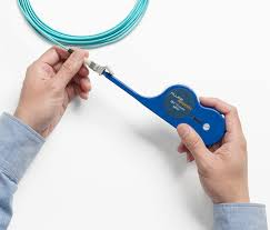
Q: How do I clean the transceiver’s optical connector?
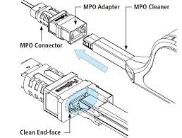
A: A QSFP transceiver and its mating cable are terminated in MPO or MTP connectors. Fiber cleaning equipment is available in the market for easy cleaning of both cable connectors and transceiver connectors.
Cleaning an MPO or MTP Connector
Similar optical fiber cleaners are available for the LC type connectors that are used with SFP+, and SFP28 transceivers.
Q: With light coming out of the connector, is there a risk of eye damage?

A: The optical transceivers of the LinkX family emit infrared, invisible light. The power is a few mW only, and the connectors have no focusing lens at the emission point, so the light beam is spread out when leaving the connector. However, you should never look directly into a connected optical cable or a transceiver plugged into a host system.
Q: why are CA-N and CA-L added to your latest generation of Nx25 GbE passive copper cables (DACs)? Which cable to choose for the 2.5 m version for which you offer both?
A: For short inter-rack communication links, direct attach copper (DAC) cables are commonly used. IEEE 802.3by specifies 3 different FEC settings, depending on the cable attenuation.
If link latency is critical for the system, then use the “CA-N” type of cable. Host systems (switches, network cards) by default disable forward error correction (FEC) for CA-N type cables.
For longer links, with loss specification > 16.48 dB cables are specified as ‘CA-S’ which require BASE-R FEC, and cables with > 22.48 dB attenuation are specified as ‘CA-L’ cables which require use of RS-FEC.
Length and thickness of copper cables both affect the attenuation. Attenuation increases with cable length, but decreases with cable thickness. Thinner cables have higher attenuation than thicker counterparts, but are less expensive, have lower weight, and are more flexible.
Q: What is FEC?
A: Forward error correction (FEC) is a process of adding an error-correcting code (ECC) to a message (‘payload’) so that this can be recovered by a receiver even when multiple errors (up to the capability of the code being used) were introduced during the process of transmission. The ECC is forwarded together with the data message. Since the receiver does not have to ask the sender for retransmission of the data, a backchannel is not required in forward error correction.
To correct errors and protect the data integrity, Forward Error Correction (or FEC) is used in 25G and higher data rates to improve data transfer throughput without the need for re-transmitting the data. FEC is a digital processing technique which effectively reduces the number of errors and helps extend the reach capability of both copper and optical cables. There are a number of FEC modes offering different degrees of error detection and recovery.
The IEEE 802.3by standard defines Clause 91 with Reed-Solomon FEC (RS-FEC) for 25 GbE (ethernet) to support most of the copper and optical interconnects. Clause 74 of the 100 GbE standard specifies BASE-R FEC, also known as fire-code FEC. FC-FEC offers a weaker error correction but with lower latency compared to RS-FEC. To achieve error free communication, the same type of FEC must be enabled on both ends of the link. Different configuration of FEC in the two host systems if one of the common interoperability problems when setting up high-speed communication links.
In Nvidia products the FEC processing takes place in the switches and network cards. Cables and transceivers are not part of FEC processing.
Q: What are N and L in the part numbers?
A: CA-N = FEC is NOT required for 0.5 m to 3 m. In Ethernet links, FEC is normally enabled, but for CA-N DACs it can be turned off by technicians to save power and latency. It is permitted but not required to use FEC.
CA-L = Long cables; require FEC for 3m-5m to ensure error free transmission.
For Nvidia systems, plugging in Nvidia DAC Type CA-N will cause the switch to automatically reduce the FEC algorithm to BASE-R FEC (that is, FireCode), saving ~ 30% in latency.
Customers can manually turn off FEC and save ~120ns per direction. The technician needs to set it up.
Since most of the traffic within a data center is up and down the rack to servers and storage, this is a big deal.
Q: What is the difference between CA-N and CA-L?
A: CA-N uses a thicker wire (26AWG) with enhanced shielding (higher cost), so it attenuates the high-speed signals less and turning off FEC is allowed.
CA-L uses a thinner wire (30AWG) with less shielding (lower cost) because the system knows FEC will be used to correct any data errors.
CA-N & CA-L only apply to 25G/50G/100G Ethernet; they do NOT apply to 100G EDR InfiniBand (which does not use FEC).
CA-N/L applies only to 25G and 100G DACs, but not to 200G or 400G DACs.
Q: How much does an AOC typically weigh?
A: In QSFP AOCs and between QSFP transceivers, a fiber cable with 8 fibers is used. This type of fiber cable weighs approximately 10 g/m. The weight per meter is practically the same for single mode and multi-mode fiber cables with the shielding used for indoor cables in data centers.
QSFP AOCs of the same length weigh the same, irrespective of the data rate.
AOC Ordering Part Number, Weight and Description
|
OPN |
Weight [g] |
Description |
|
MFS1S00-x005E |
166 |
Nvidia® active fiber cable, 200G, QSFP, LSZH, 5 m |
|
MFS1S00-x010E |
210 |
Nvidia® active fiber cable, 200G, QSFP, LSZH, 10 m |
|
MFS1S00-x020E |
283 |
Nvidia® active fiber cable, 200G, QSFP, LSZH, 20 m |
|
MFS1S00-x030E |
350 |
Nvidia® active fiber cable, 200G, QSFP, LSZH, 30 m |
|
MFA1A00-C050 |
572 |
Nvidia® active fiber cable, 200G, QSFP, LSZH, 50 m |
|
MFA1A00-C100 |
1074 |
Nvidia® active fiber cable, 200G, QSFP, LSZH, 100 m |
Q: How much does a PCC (DAC) weigh?
A: Different types of cables are used for different PCCs. In the MCP1600 EDR PCCs, an 8-pair 24 AWG cable is used. This cable weighs 114 g/m. Add 40 g per QSFP connector/shell at each end.
PCC (DAC) Ordering Part Number, Weight and Description (Examples)
|
OPN |
Weight [g] |
Description |
|
MCP1650-x00AE30 |
116 |
Nvidia® Passive Copper Cable, 200G, QSFP, LSZH, 0.5 m |
|
MCP1650-x001E30 |
203 |
Nvidia® Passive Copper Cable, 200G, QSFP, LSZH, 1 m |
|
MCP1650-x01AE30 |
290 |
Nvidia® Passive Copper Cable, 200G, QSFP, LSZH, 1.5 m |
|
MCP1650-x002E26 |
300 |
Nvidia® Passive Copper Cable, 200G, QSFP, LSZH, 2 m |
|
MCP1650-x003E26 |
387 |
Nvidia® Passive Copper Cable, 200G, QSFP, LSZH, 3 m |
In the MCP2M00 PCC, a 2-pair 30 AWG cable is used. It weighs 24 g/m. Add 20 g per SFP28 connector/shell at each end. This adds up to approximately 90 g for the 2 m MCP2M00-002 SFP28 cable.
We can provide the weight of other cables on request.
Q: How much does a transceiver weigh?
A: The weight depends on the size, i.e. the form factor.
An SFP transceiver weighs approximately 20 g.
A QSFP transceiver weighs approximately 43 g, excluding the protective covers.
An OSFP transceiver weighs approximately 260 g excluding protective covers.
The QSA (MAM1Q00A-QSA(28), QSFP to SFP) adapter weighs approximately 25 g.
Q: Why do some of your datasheets have two specifications of a cable’s minimum bend radius?
A: Cables typically tolerate a sharper bending (more stress) in the ‘middle’ of the cable, than by the strain relief and connector. The assembly bend radius indicates the larger minimum bend radius to use when bending the cable where it comes out of the connector shell.
Q: Why do different cables have different definition of their length?
A: When you measure the distance from port to port, you need a cable that is longer since part of the connector is inserted into the switch/NIC. For some cables the length is defined to exclude the inserted part, for others the length is tip-to-tip.
Q: Why don’t you have a common fire certification covering all national standards for your cables?
A: Different parts of the world apply different regulatory standards, of which some apply to ‘installation material’. Our longer fiber cables can be considered installation material while shorter patch cables and copper cables are not. Certification of cables is costly and time consuming, hence, it is done based on demand from different regions or customers.