Cable Installation
The switch uses industry standard QSFP InfiniBand cables which are available from Mellanox Technologies. The Mellanox proprietary QSFP cables support full 100+100Gb/s (EDR), 56+56Gb/s (FDR), 40+40Gb/s (FDR10), 40+40Gb/s (QDR), 20+20Gb/s (DDR) and 10+10Gb/s (SDR) bidirectional wire speed of the switch ports. All InfiniBand QSFP connections are made to the leaf modules. Each leaf has 18 InfiniBand QSFP connectors in two rows, which are numbered 1-18. See Port Connector Interfaces for port numbering.
If maximum cable lengths are exceeded data transfer will be reduced and the bit error rate will increase.
EDR is only guaranteed to work with approved Mellanox cables.
All cables can be inserted or removed with the unit powered on. To insert a cable, press the connector onto the port receptacle until the connector is firmly seated. The orange LED indicator above the port will light when the physical connection is established (when both ends of the cable are properly connected to working devices). Allow 15 seconds for link to get up. To remove, disengage the lock and slowly pull the connector away from the port receptacle.
For a valid physical connection both ends of the cable must be connected to working devices.
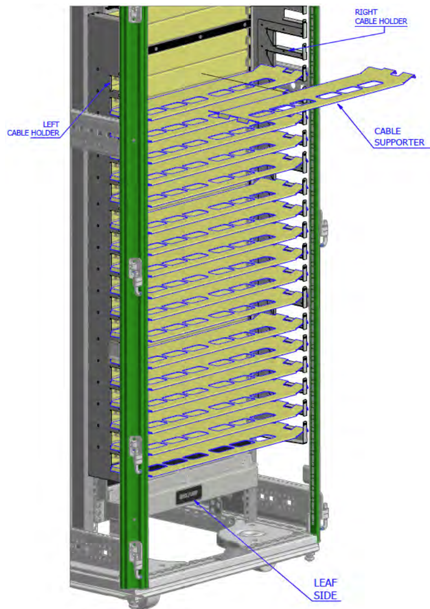
Careful to not impede the airflow through the ventilation holes next to the InfiniBand ports. Use cable lengths which allow routing horizontally around to the side of the chassis before bending upward or downward in the rack.
After connecting the power cords, you may place the 18 cable supporters onto the cable holders.
Cable Supporter Placement
Supported Approved Cables
For a list of approved cables for this switch see the Mellanox approved cable list at http://www.mellanox.com/page/cables?mtag=cable_overview.
Cable Power Classes
Chassis and switches need to be able to dissipate the heat generated by high power I/O cables and modules. Mellanox CS75x0 series chassis are rated for cables up to class 4 as per the SFF committee classification (SFF-8436.PDF).
This section assumes that the power cords are not connected to the power main. Once system assembly is finished please refer to Chassis Power Up to power the system up.
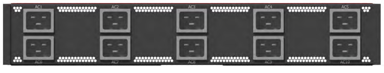
The switch includes 10 hot-swap power supply units (PSUs). Each PSU has its dedicated AC inlet. The system uses C20 type inlets. The design enables optional use of separate main and backup AC feeds. The AC power source should comply with 180-265VAC 50Hz or 60Hz characteristics.
C19 to C20 type power cords, 15A rated, should be used to connect system to AC power. The maximum power consumption of each power supply is 12A. Ensure all 10 power cords are firmly connected to inlets.
AC Inlets
Make sure that the power cords are compatible with your outlets. Power cords for different countries can be ordered from Mellanox.
Make sure that the outlets and circuits are not overloaded. Spread out the load over at least two or three circuits or use a 3 phase circuit.