Interfaces
The LEDs are placed on the chassis for the convenience of the IT manager. All chassis conditions and management options are available and controllable through the management software, either CLI or WebUI.
It is recommended that all of the chassis subsystems be maintained and managed through the management software.
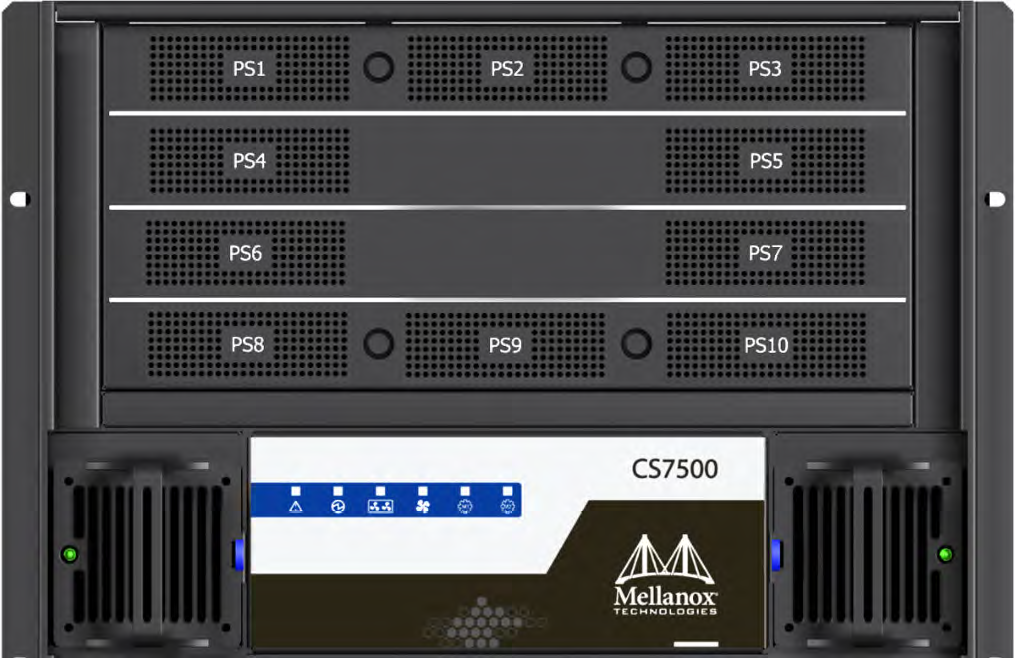
Power Supply Unit LEDs
The PSUs are on the spine side of the chassis at its upper side and are behind two cover panels. The plugs for these PSUs are on the leaf side of the chassis.
Each power supply unit has the following LED indicators.
Power Supply Unit Status Indications

AC OK – LED indicator
Green – when input voltage is 85VAC < Vin < 270VAC
Off – when input voltage is 85VAC > Vin or Vin > 270VAC
DC OK – LED indicator
Green – when output voltage above 90% +/- 5% of 48VDC
Red – when output voltage fallen below 90% +/- 5% of 48VDC
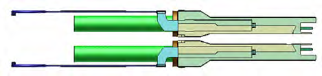
CS7500 PSU Cover
System AC Power Interface
Each PSU in the switch system has a dedicated AC inlet. The inlets are numbered, 1 through 10, corresponding to the numbers on the PSU covers. The system utilizes C19/C20 AC inlet standard where C20 socket is installed on the system. A C19-to-C20 power cord is provided with the system. An appropriate Power Delivery Unit (PDU) should be installed to interface with the system.
Leaf Module LED Indicators
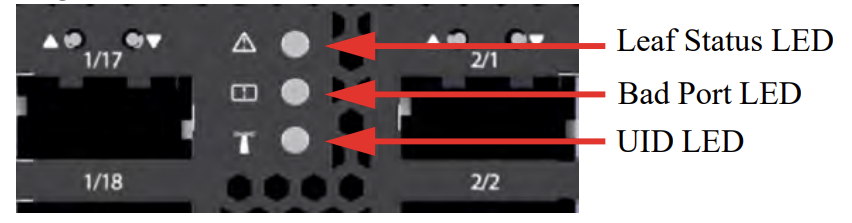
Status LED
The Status LED is located in the middle of the leaf to allow easier visibility when all cables are installed.
The leaf Status indicator LED has the following LED assignment:
|
LED Condition |
Description |
|
Off |
No power to the leaf |
|
Green: Solid |
Leaf is up and running |
|
Green: Flashing |
Leaf is booting or being restored to factory default |
|
Amber: Solid |
Fatal error |
Bad Port LED
The Bad Port LED
|
LED Condition |
Description |
|
Off |
OK: All ports are up and running |
|
Amber: Flashing |
Error: One or possibly more ports has just received a symbol error |
This LED shows symbol errors. Possible causes for this are:
• bad cable
• bad connection
• bad connector
This LED lights up when one or more ports is receiving a symbol error. The LED immediately goes off until the next symbol error is received.
UID LED Switch Identifier
The UID LED is a debug feature that will become available to customers in the near future. For details please contact Mellanox Technologies support.
Leaf Module Port Connector LED Assignment
Above the ports are two LEDs one for the upper port

and one for the lower port

. Each port has a single 2 color LED. The table below presents the link status according to the LED condition.
Connector Physical and Logical Link Indications
|
LED Condition |
Description |
|
Off |
No power to the port |
|
Green: Solid |
Logical link up |
|
Green: Flashing |
Data activity: Flashing frequency is proportional to data transfer speed |
|
Amber: Solid |
Physical link up |
|
Amber: Flashing |
A problem with the physical link |
The LED indicator, corresponding to each data port, will light orange when the physical connection is established (that is, when the unit is powered on and a cable is plugged into the port with the other end of the connector plugged into a functioning port). When a logical connection is made the LED will change to green. When data is being transferred the light will blink green.
The switch does not provide a visual means to indicate the port speed configuration (SDR, DDR, QDR, FDR, or EDR) and/or the link width (1X or 4X). The speed and link width configurations can be retrieved using management software.
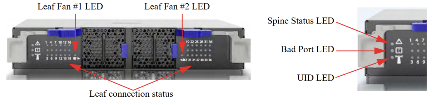
Spine Module LED Indicators
Each leaf module is connected by links to each spine module. Each spine has the following LEDs.
• One status LED for the spine health
• Two status LED for the spine fan modules, one per module
• 36 status LEDs showing the existence of leaf to spine connections
• One Bad Port LED showing symbol errors in the data stream
• One UID LED that can be lit to identify an individual spine
The 36 LEDs on each spine are divided by the number of leafs and the result (N) is the number of connections from each leaf that are connected to the spine. All spines must be installed and working to ensure that full BW exists between nodes. The maximum number of connections from each leaf is 1. If the (number of leafs) x (the maximum number of connections per leaf) is less than 36 then some of the leaf to spine connection LEDs may be OFF.
The status LEDs for the spine and their descriptions are shown in the table below. The LEDs indicate as follows.
Status LED
The table below shows the spine status according to the LED condition:
|
LED Condition |
Description |
|
Off |
No power to the spine |
|
Green: Solid |
Spine is up and running |
|
Green: Flashing |
Spine is powering up or being restored to factory default |
|
Amber: Solid |
Fatal error |
Fan LED
For each fan drawer in the spine there is a status LED. The spine fan indicator LED has the following LED assignment:
|
LED Color |
Description |
|
Green: Solid |
Spine fan is OK |
|
Amber: Solid |
One of the fans is not working and needs replacement |
Spine to Leaf IB Connection Status LEDs
The leaf connection status on each spine displays the condition of the connection between the spine and each leaf. There is a minimum of one LED per leaf per spine and a maximum of 1 LED per leaf. These LEDs indicate a valid connection between a leaf and a spine. The table below shows the leaf to spine status according to the LED condition:
|
LED Color |
Description |
|
Off |
Link is down |
|
Green: Solid |
Logical connection |
|
Green: Flashing |
Data activity |
|
Amber: Solid |
Physical connection established |
Bad Port LED
The Bad Port LED
|
LED Condition |
Description |
|
Off |
OK: No ports have received symbol errors recently |
|
Amber: Flashing |
Error: One or possibly more ports has just received a symbol error |
This LED shows symbol errors. Possible causes for this are:
• bad cable
• bad connection
• bad connector
This LED lights up when one or more ports is receiving a symbol error. The LED immediately goes off until the next symbol error is received.
UID LED Switch Identifier
The UID LED is a debug feature that will become available to customers in the near future. For details please contact Mellanox Technologies support.
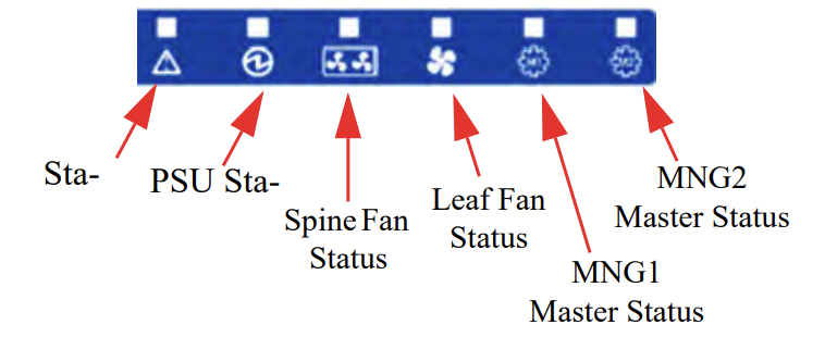
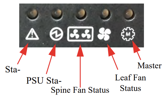
Spine Side Panel Display LED Indicators
The spine side panel display has LEDs that show the chassis condition.
|
Spine-Side Panel LED Display for Normal Operation |
|||
|
LED |
Condition |
Description |
Normal State |
|
Status |
Off |
No power |
Green |
|
Green |
System is up and running |
||
|
Green: Flashing |
System booting/restore factory default in progress |
||
|
Amber |
Fatal error |
||
|
PSU Status |
Off |
No power |
Green |
|
Green |
Normal operational |
||
|
Amber |
PS fault detected - check individual power supplies for fault indications |
||
|
Spine Fan Status |
Off |
No power |
Green |
|
Green |
Normal operation |
||
|
Amber |
Fatal error in one or more of the spine fans - check individual spine fan LEDs for fault indications |
||
|
Leaf Fan Status |
Off |
No power |
Green |
|
Green |
Normal operation |
||
|
Amber |
Fatal error in one or more of the leaf fans - check individual leaf fan LEDs for fault indications |
||
|
MNG1 Master Status |
Off |
|
Green |
|
Green |
Management module is up and operating as master |
||
|
Amber |
Slave management module not installed |
||
|
MNG2 Master Status |
Off |
|
Off |
|
Green |
Management module is up and operating as master |
||
Management Module LED Indicators
The management module LEDs display the switch system operating conditions.
|
Management LED Display for Normal Operation |
|||
|
LED |
Condition |
Description |
Normal State |
|
Status LED: Shows the status of the chassis. |
Off |
No power |
Green |
|
Green |
System is up and running |
||
|
Green: Flashing |
System booting/restore factory default in progress |
||
|
Amber |
System error - attention needed (e.g. overheating, diagnostics fail, CPU hang, HW fail, overheat-critical) |
||
|
PSU Status |
Off |
No power |
Green |
|
Green |
Normal operation |
||
|
Amber |
PS fault detected - check individual power supplies for fault indications |
||
|
Spine Fan Status |
Off |
No power |
Green |
|
Green |
Normal operation |
||
|
Amber |
Fatal error in one or more of the spine fans - check individual spine fan LEDs for fault indications |
||
|
Leaf Fan Status |
Off |
No power |
Green |
|
Green |
Normal operation |
||
|
Amber |
Fatal error in one or more of the leaf fans - check individual leaf fan LEDs for fault indications |
||
|
Master |
Off |
This management module is not the master |
Green |
|
Green |
Management module is operating as a master |
||
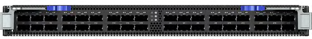
Port Connector Interfaces
The connector side of the switch has 18 leaf modules and each leaf module has 36 QSFP28 ports. The ports on each leaf module are placed in two rows, 18 ports to a row. The ports are labeled as shown in the figure below. The bottom row ports are flipped from the top row as shown.
Port Numbering
Top and Bottom Ports
These switches come with the air flow pattern of air entering through the spine side and exiting through the connector side.
All Switch-IB™ and Switch-IB™ 2 based switch systems are designed for active cables with a max power per module of 3.5W. This is power level 4 according to the QSFP Public Specification.
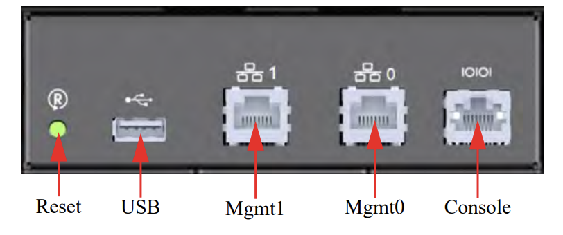
The switch system requires at least one management module. The management module has 6 interfaces to connect to the director switch system. They are:
1 I2C/CONSOLE port – this is an I2C/RS232 connector for connecting to a host machine
2 MGMT – this is an Ethernet connector
1 USB port
1 RST – reset button
1 QSFP port – for debug purposes only
Management Module Interfaces
I2C/Console (RS232)
The console port is used during the installation process to configure the chassis for remote management. Connect this port to a local host using the harness supplied with the chassis. See the MLNX-OS® User Manual for the initial configuration procedure. RS232 connection should be configured for 115200Kb baud-rate.
Apart from the initial configuration, I²C interface is made exclusively for debugging and troubleshooting. Only FAEs are authorized to connect through it.
Only original Mellanox cables supplied with the switch package can be used to connect a switch system to the server.
Connecting any cable other than the Mellanox supplied console cable may cause an I²C hang. Using uncertified cables may damage the I²C interface.
Refer to the Replacement Parts Ordering Numbers appendix for harness details.
Management
The management ports are 1Gb/s Ethernet (1GbE) ports for remote management. Any remote terminal connected to the Ethernet port can then be used to manage the fabric and chassis.
USB
The USB 2.0 port can be used to upload new software using any storage device that has a USB connector.
Reset – RST
The Reset button resets the chassis management module when the button is pushed. When the button is held down for 15 seconds the management module is reset and the password deleted.
On a switch system with two management modules, the slave management module must be extracted, then the aforementioned procedure must be performed on the master management module. Once the system reloads, the slave management module may be reinserted.
Do not use a sharp pointed object such as needle or push pin for pressing the Reset button. Sharp objects can cause damage, use a flat object such as a paper clip.
This button resets the CPU of the management module. A quick push of this button performs this reset. When the reset button is pushed on the master management module this management module is reset becoming the slave and the other management module becomes the master. If there is only one management module in the chassis all of the leafs and ports are reset by bringing them down and powering them up when the reset button is pushed. When the button is held down for 15 seconds the management module is reset and the password is deleted. You will then be able to enter without a password and make a new password for the user “admin”.