Installation
Installation and initialization of this chassis is a simple process which requires attention to the regular mechanical, power, and thermal precautions for rack-mounted equipment. The chassis comes only with the power supplies and fans pre-installed. The rest of the openings are populated with blanks. All of the leafs, spines, and management modules are shipped in a separate package.
The chassis requires initial configuration to get the chassis and fabric management up and running through remote management.
This chassis can be installed in standard 19” racks that have depths between 715-850mm between the vertical supports of the rack.
This unit is intended for installation in a restricted access location. A restricted access area can be accessed only through the use of a special tool, lock and key, or other means of security .
Unless otherwise specified, Mellanox products are designed to work in an environmentally controlled data center with low levels of gaseous and dust (particulate) contamination.
The operation environment should meet severity level G1 as per ISA 71.04 for gaseous contamination and ISO 14644-1 class 8 for cleanliness level.
Prior to the installation, please review the safety warnings. Note that not all warnings may apply to all models.
Safety warnings are provided here in the English language. For safety warnings in other languages, refer to the Director Switch Installation Safety Instructions document available on mellanox.com.
Safety Warnings (English)

Installation Instructions
Read all installation instructions before connecting the equipment to the power source.

Bodily Injury Due to Weight
Use enough people to safely lift this product.
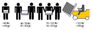

Heavy Equipment
This equipment is heavy and should be moved using a mechanical lift to avoid injuries.
Installation in Restricted Access Location
This unit is intended for installation in a Restricted Access Location.

Risk of Electric Shock!
With the fan module removed power pins are accessible within the module cavity.
Do not insert tools or body parts into the fan module cavity.
Over-temperature
This equipment should not be operated in an area with an ambient temperature exceeding the maximum recommended: 45°C (113°F).
For CS85xx systems: This equipment should not be operated in an area with an ambient temperature exceeding the maximum recommended: 35°C (95°F).
Moreover, to guarantee proper ventilation, allow at least 8cm (3 inches) of clearance around the ventilation openings.
Stacking the Chassis
The chassis should not be stacked on any other equipment. If the chassis falls, it can cause bodily injury and equipment damage.
Redundant Power Supply Connection - Electrical Hazard
This product includes a redundant power or a blank in its place. In case of a blank power supply, do not operate the product with the blank cover removed or not securely fastened.
Double Pole/Neutral Fusing
This system has double pole/neutral fusing. Remove all power cords before opening the cover of this product or touching any internal parts.
Multiple Power Inlets
Risk of electric shock and energy hazard. The PSUs are all independent. Disconnect all power supplies to ensure a powered down state inside of the switch platform.
During Lightning - Electrical Hazard
During periods of lightning activity, do not work on the equipment or connect or disconnect cables.

Copper Cable Connecting/Disconnecting
Copper cables are heavy and not flexible, as such they should be carefully attached to or detached from the connectors. Refer to the cable manufacturer for special warnings/instructions.

Rack Mounting and Servicing
When this product is mounted or serviced in a rack, special precautions must be taken to ensure that the system remains stable. In general you should fill the rack with equipment starting from the bottom to the top.

Equipment Installation
This equipment should be installed, replaced, and/or serviced only by trained and qualified personnel.

Equipment Disposal
Disposal of this equipment should be in accordance to all national laws and regulations.

Local and National Electrical Codes
This equipment should be installed in compliance with local and national electrical codes.
Installation Codes
This device must be installed according to the latest version of the country national electrical codes. For North America, equipment must be installed in accordance to the applicable requirements in the US National Electrical Code and the Canadian Electrical Code.
Battery Replacement
Warning: Replace only with UL recognized battery, certified for maximum abnormal charging current not less than 4mA.
For CS85xx systems: Replace only with UL recognized battery, certified for maximum abnormal charging current not less than 10mA abnormal charge or 9mA.
There is a risk of explosion should the battery be replaced with a battery of an incorrect type. Dispose of used batteries according to the instructions.
UL Listed and CSA Certified Power Supply Cord
For North American power connection, select a power supply cord that is UL Listed and CSA Certified, 3 - conductor, [16 AWG], terminated with a molded plug rated at 125 V, [13 A], with a minimum length of 1.5m [six feet] but no longer than 4.5m.
For European connection, select a power supply cord that is internationally harmonized and marked “<HAR>”, 3 - conductor, minimum 1.0 mm2 wire, rated at 300 V, with a PVC insulated jacket. The cord must have a molded plug rated at 250 V, 10 A.
For CS75xx and CS85xx systems:
For North American power connection, select a power supply cord that is UL Listed and CSA Certified, 3 - conductor, [14 AWG], terminated with a molded plug rated at 250 V, [16 A], with a minimum length of 1.5m [six feet] but no longer than 4.5m.
For European connection, select a power supply cord that is internationally harmonized and marked “<HAR>”, 3 - conductor, minimum 1.5 mm2 wire, rated at 300 V, with a PVC insulated jacket. The cord must have a molded plug rated at 250 V, 16 A.
High Leakage Current
Warning: High leakage current; Earth connection essential before connecting supply.
Add GND Connection Information
Before connecting this device to the power line, the protective earth terminal screws of this device must be connected to the protective earth in the building installation.
(GND Connection Information):
The building installation shall provide a means for a connection to protective earth; and the equipment shall be permanently connected to that by a service person.
A SERVICE PERSON shall check whether or not the socket - outlet from which the equipment is to be powered provides a connection to the building protective earth. If not, the SERVICE PERSON shall arrange for the installation of a PROTECTIVE EARTHING CONDUCTOR from the separate protective earthing terminal to the protective earth wire in the building. The equipment shall be installed in area where equi-potential bonding exists (such as a telecommunication centre or a dedicated computer room).
Installation Codes
This device must be installed according to the latest version of the country national electrical codes. For North America, equipment must be installed in accordance to the applicable requirements in the US National Electrical Code and the Canadian Electrical Code.
Interconnection of Units
Cables for connecting to the unit RS232 and Ethernet Interfaces must be UL certified type DP-1 or DP-2. (Note- when residing in non LPS circuit)

Hazardous Radiation Exposure
Caution – Use of controls or adjustment or performance of procedures other than those specified herein may result in hazardous radiation exposure.
CLASS 1 LASER PRODUCT and reference to the most recent laser standards IEC 60 825-1:1993 + A1:1997 + A2:2001 and EN 60825-1:1994+A1:1996+ A2:2001
Proper Enclosure
A suitable electrical, mechanical and fire enclosure shall be provided by the end product manufacturer and or the end user.
Overcurrent Protection
A readily accessible Listed branch circuit overcurrent protective device rated 20A must be incorporated in the building wiring.

Do Not Use the Switch as a Shelf or Work Space
Caution: Slide/rail mounted equipment is not to be used as a shelf or a work space. The rails are not intended for sliding the unit away from the rack. It is for permanent installation at final resting place only, not used for service and maintenance

WEEE Directive
According to the WEEE Directive 2002/96/EC, all waste electrical and electronic equipment (EEE) should be collected separately and not disposed of with regular household waste. Dispose of this product and all of its parts in a responsible and environmentally friendly way.

Country of Norway Power Restrictions
This unit is intended for connection to a TN power system and an IT power system of Norway only.
The following are Mellanox recommendations.
Recommended ambient temperature in the System room is 20±5ºC. Recommended humidity range is 40%±15% without condensing.
It is highly recommended that the installation sites be as isolated as possible from all sources of radio transmissions and electrical interference.
It is highly recommended that the installation site building be equipped with a lightning rod.
It is highly recommended that the installation site be equipped with smoke detectors and a fire alarm warning system.
The system requires a KVA rated UPS system. It is recommended that a UPS system be installed to protect the equipment in the event of unexpected power failure.
Make sure that the outlets and circuits will not be overloaded. Spread out the load over at least two or three circuits or use a 3 phase circuit.
The system’s components are shipped as specified below.
Chassis Crate
The switch system chassis is shipped in a dedicated crate which includes the following boxes:
Switch system chassis with the leaf fan and power supply modules already installed.
Chassis installation kit (see Chassis Installation Kit Items)
Cable holders (see Cable Management Installation Kit Parts)
One box containing 6 smaller boxes with cable shelves
1 box containing 104 power cords (250V 16A 2m, C19 to C20, USA UL Standard)
The management, spine, and leaf modules are shipped separately.
To completely populate this chassis, one requires 2 management module boxes, 18 spine module boxes, and 18 leaf module boxes.
Spine Module Boxes
Each box contains 1 spine module with its fan modules already installed.
This unit is intended for installation in a restricted access location. A restricted access area can be accessed only through the use of a special tool, lock and key, or other means of security.
Leaf Module Boxes
Each box contains 1 leaf module.
Management Module Boxes
Each box contains 1 management module and 1 RJ45-to-DB9 cable.