Supported Interfaces
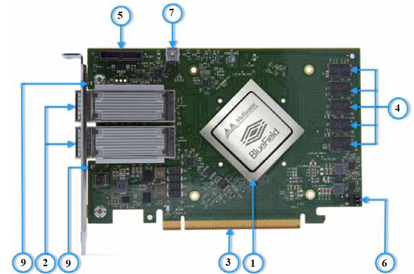
The below figures show the component and print sides of BF1500 Controller Card. Each numbered interface that is referenced in the figures is described in the following table with a link to detailed information.
The BF1500 Controller Card include special circuits to protect from ESD shocks to the card/server when plugging copper cables
The below figures are for illustration purposes only and might not reflect the current revision of the BF1500 Controller Card.
BF1500 Controller Card Interfaces - Component Side
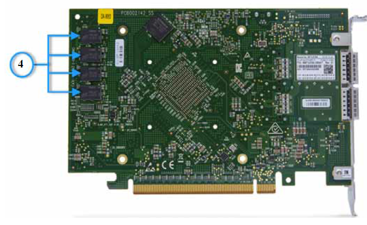
BF1500 Controller Card Interface - Print Side
Item | Interface | Description |
1 | Mellanox BlueField SoC 16 cores | |
2 | Ethernet traffic is transmitted through the BF1500 Controller Card QSFP28 connectors. The QSFP28 connectors allow for the use of modules, optical and passive cable interconnect solutions | |
3 | PCIe Gen 3.0/4.0 through an x16 edge connector | |
4 | Single channel with 8 DDR4 8 bit + ECC (64bit + 8bit ECC) | |
5 | BMC connection for remote management | |
6 | Access to Arm console. | |
6 | Mounted on the Controller Card for OS image loading | |
7 | Arm debug tool | |
8 | One bi-color LED per port for the link and physical status |
BlueField System-on-Chip (SoC)
BlueField is a Mellanox family of advanced SoC solutions that integrate a coherent mesh of 64-bit Arm v8 A72 cores, a ConnectX network adapter front-end and a PCI Express switch into a single chip. The powerful SoC architecture includes an ARMv8 multicore processor array and enables customers to develop sophisticated applications and highly differentiated feature sets. BlueField leverages the rich ARM software ecosystem and introduces the ability to offload the x86 software stack.
At the heart of BlueField is the ConnectX-5 network offload controller with RDMA and RDMA over Converged Ethernet (RoCE) technology, delivering cutting-edge performance for networking and storage applications such as NVMe over Fabrics. Advanced features include an embedded virtual switch with programmable access lists (ACLs), transport offloads and stateless encaps/decaps of NVGRE, VXLAN, and MPLS overlay protocols.
Ethernet QSFP28 Interface
The network ports of BF1500 Controller Card are compliant with the IEEE 802.3 Ethernet standards listed in Features and Benefits. Ethernet traffic is transmitted through the cards' QSFP28 connectors.
PCI Express Interface
The BF1500 Controller Card supports PCI Express Gen 3.0/4.0 (1.1 and 2.0 compatible) through an x16 edge connector. The device is a slave responding to the PCIe bus operations (end-point). Please refer to PCI Express Pins Description for pinouts description.
The following lists PCIe interface features:
PCIe Gen 3.0 and 4.0 compliant, 2.0 and 1.1 compatible
2.5, 5.0, or 8.0, or 16.0 GT/s link rate x16 lanes
Auto-negotiates to x16, x8, x4, x2, or x1
Support for MSI/MSI-X mechanisms
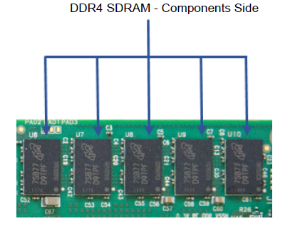
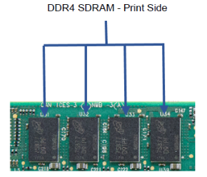
DDR4 SDRAM On-Board Memory
The BF1500 Controller Card incorporates a single channel DDR4 SDRAM memory with 8 components of 8 bit + ECC (64bit + 8bit ECC), 16GB @2400MT/s.
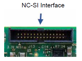
NC-SI Management Interface
The BlueField Controller Card enables the connection of a Baseboard Management Controller (BMC) to a set of Network Interface Controller (NICs) for the purpose of enabling out-of-band remote manageability. The NC-SI management is supported over RMII and has a connector on the Controller Card. Please refer to NC-SI Management Interface for pins.
3 Pin Header Interface
The 3 pin header interface enables access to the Arm console through UART0 through the following pins:
Pin # 1 - UART0 RX
Pin # 2 - GND
Pin # 3 - UART0 TX
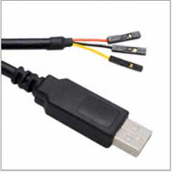
UART Interface Connectivity
The USB to UART cable that supports TTL voltage levels can be used to connect the UART Interface. See an example of TTL 3.3V voltage levels cable in the below figure.
It is prohibited to directly connect any RS-232 cable! Only TTL 3.3V voltage level cables are supported!
USB to UART Cable - Example
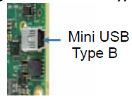
Mini USB Type B Interface
The BF1500 Controller Card uses a Mini USB Type B. The USB connector is mounted on the card. The purpose of the USB connector is loading operating system images for the operating systems. In order to use this interface, please use a standard Mini USB Type-B to Mini USB Type A cable.
JTAG CoreSight 10 Interface
The BF1500 Controller Card uses JTAG CoreSight 10-Pin Header. The purpose of the JTAG CoreSight 10 is for debugging the Arm with Arm DSTREAM debug tool. For JTAG CoreSight 10 pins, please refer JTAG CoreSight 10.
LEDs Interface
There is a one bi-color I/O LED per port to indicate link and physical status.
Physical and Logical Link Indications (Ethernet Mode)
LED Color and State | Description |
Off | A link has not been established |
Blinking Amber(a) | 4 Hz blinking amber indicates a problem with the link |
Solid Green | Indicates a valid link with no active traffic |
Blinking Green | Indicates a valid logical link with active traffic |
Note a. 1Hz Blinking amber occurs due to running a beacon command for locating the adapter card.