Hardware Installation
Installation and initialization of the BlueField BF1500 Controller Card require attention to the mechanical attributes, power specification, and precautions for electronic equipment.
Safety warnings are provided here in the English language. For safety warnings in other languages, refer to the BF1500 Controller Card Installation Safety Instructions.
Please observe all safety warnings to avoid injury and prevent damage to system components. Note that not all warnings are relevant to all models.
Note that not all warnings are relevant to all models.

| General Installation Instructions |

| Jewelry Removal Warning |
|
| Over-temperature |
|
| During Lightning - Electrical Hazard |
|
| Copper Cable Connecting/Disconnecting |
|
| Equipment Installation |
|
| Equipment Disposal |
|
| Local and National Electrical Codes |

| Hazardous Radiation Exposure
|
The installation procedure of BlueField BF1500 Controller Card involves the following steps:
Step | Procedure | Direct Link |
1 | Check the system’s hardware and software requirements. | Refer to System Requirements |
2 | Pay attention to the airflow consideration within the host system | Refer to Airflow Requirements |
3 | Follow the safety precautions | Refer to Safety Precautions |
4 | Unpack the package | Refer to Pre-Installation Checklist |
5 | Follow the pre-installation checklist | Refer to Pre-Installation Checklist |
6 | (Optional) Replace the full-height mounting bracket with the supplied short bracket | Refer to Bracket Replacement Instructions |
7 | Install the BF1500 Controller Card | Refer to Installation Instructions |
8 | Connect cables or modules to the card | Refer to Cables and Modules Installation |
9 | Identify the BF1500 Controller Card in the system |
Hardware Requirements
Unless otherwise specified, Mellanox products are designed to work in an environmentally controlled data center with low levels of gaseous and dust (particulate) contamination.
The operation environment should meet severity level G1 as per ISA 71.04 for gaseous contamination and ISO 14644-1 class 8 for cleanliness level.
The user must install the BlueField Controller Card into a high power PCI Express x8 slot as the card consumes up to 55W.
A system with a PCI Express high power slot that supports 75W is required for installing the card.
Airflow Requirements
BlueField BF1500 Controller Card is offered with one airflow pattern: from the heatsink to the network ports, as described in the below figure.
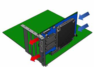
It is prohibited to use port-to-heatsink airflow as it may cause damage to the BlueField BF1500 Controller Card.
Please refer to the Specifications section for airflow numbers for each specific card model.
Software Requirements
See Operating Systems/Distributions section under the Introduction section.
Software Stacks - The BF1500 Controller Card is shipped with Linux based Operating System burned on it which includes all needed drivers. For more information, please refer to the BlueField Software User Manual.
The BF1500 Controller Card being installed in a system that operates with voltages that can be lethal. Before opening the case of the system, observe the following precautions to avoid injury and prevent damage to system components.
Remove any metallic objects from your hands and wrists.
Make sure to use only insulated tools.
Verify that the system is powered off and is unplugged.
It is strongly recommended to use an ESD strap or other antistatic devices.
Check against the package contents list that all the parts have been sent. Check the parts for visible damage that may have occurred during shipping. Please note that the cards must be placed on an antistatic surface.
Verify that your system meets the hardware and software requirements stated above.
Shut down your system if active.
Turn off the power to the system, and disconnect the power cord. Refer to the system documentation for instructions. Before you install the BlueField BF1500 Controller Card, make sure that the system is disconnected from power.(Optional) Check the mounting bracket on the BlueField BF1500 Controller Card.
If required for your system, replace the full-height mounting bracket that is shipped mounted on the card with the supplied low-profile bracket. Refer to Bracket Replacement Instructions.
The BF1500 Controller Card is usually shipped with an assembled high-profile bracket. If this form factor is suitable for your requirements, you can skip the remainder of this section and move to Installation Instructions. If you need to replace the high-profile bracket with the short bracket that is included in the shipping box, please follow the instructions in this section.
Due to risk of damaging the EMI gasket, it is not recommended to replace the bracket more than three times.
To replace the bracket you will need the following parts:
The new brackets of the proper height
The 2 screws saved from the removal of the bracket
Removing the Existing Bracket
Using a torque driver, remove the two screws holding the bracket in place.
ImportantBe careful not to put stress on BF1500 Controller Card LEDs.
Separate the bracket from the BF1500 Controller Card.
Save the two screws.
Installing the New Bracket
Place the bracket onto the card until the screw holes line up.
ImportantDo not force the bracket onto the BF1500 Controller Card.
Screw on the bracket using the screws saved from the bracket removal procedure above.
ImportantUse a torque driver to apply up to 2 lbs-in torque on the screws.
This section provides detailed instructions on how to install your BF1500 Controller Card in a system.
Please note that the following figures are for illustration purposes only.
Open the system case.
Place the BF1500 Controller Card in an available PCI Express slot.
ImportantThe BlueField BF1500 Controller Card should be installed in a high power PCI Express x8 slot as the card consumes up to 55W.

Applying even pressure at both corners of the card, insert the BF1500 Controller Card into the PCI Express slot until firmly seated.
ImportantDo not use excessive force when seating the card, as this may damage the system or the BF1500 Controller Card.

When the BF1500 Controller Card is properly seated, the port connectors are aligned with the slot opening, and the BF1500 Controller Card faceplate is visible against the system chassis.

Secure the BF1500 Controller Card with the screw.

Close the system case.
To uninstall the BF1500 Controller Card card, see Uninstalling the Card.
Cable Installation
All cables can be inserted or removed with the unit powered on.
To insert a cable, press the connector into the port receptacle until the connector is firmly seated.
Support the weight of the cable before connecting the cable to the BF1500 Controller Card card. Do this by using a cable holder or tying the cable to the rack.
Determine the correct orientation of the connector to the card before inserting the connector. Do not try and insert the connector upside down. This may damage the BF1500 Controller Card card.
Insert the connector into the BF1500 Controller Card card. Be careful to insert the connector straight into the cage. Do not apply any torque, up or down, to the connector cage in the BF1500 Controller Card card.
Make sure that the connector locks in place.
WarningWhen installing cables make sure that the latches engage.
ImportantAlways install and remove cables by pushing or pulling the cable and connector in a straight line with the card.
After inserting a cable into a port, the Green LED indicator will light when the physical connection is established (that is, when the unit is powered on and a cable is plugged into the port with the other end of the connector plugged into a functioning port). See LED Interface under the Interfaces section.
After plugging in a cable, lock the connector using the latching mechanism particular to the cable vendor. When data is being transferred the Green LED will blink. See LED Interface under the Interfaces section.
Care should be taken as not to impede the air exhaust flow through the ventilation holes. Use cable lengths which allow for routing horizontally around to the side of the chassis before bending upward or downward in the rack.
To remove a cable, disengage the locks and slowly pull the connector away from the port receptacle. LED indicator will turn off when the cable is unseated.
Network Adapter Environment
On Windows
Open Device Manager on the server. Click Start => Run, and then enter “devmgmt.msc”.
Expand System Devices and locate your BF1500 Controller Card.
Right click the mouse on your BF1500 Controller Card’s row and select Properties to display the BF1500 Controller Card properties window.
Click the Details tab and select Hardware Ids (Windows 2012/R2/2016) from the Properties pull-down menu.
In the Value display box, check the fields VEN and DEV (fields are separated by ‘&’). In the display example above, notice the sub-string “PCI\VEN_15B3&DEV_A2D2/A2D3”: VEN is equal to 0x15B3 - this is the Vendor ID of Mellanox Technologies; and DEV is equal to A2D2 or A2D3- this is a valid Mellanox Technologies PCI Device ID.
If the PCI device does not have a BF1500 Controller Card ID, return to Step 2 to check another device
On Linux
Get the device location on the PCI bus by running lspci and locating lines with the string
“Mellanox Technologies”:
            lspci |grep -i Mellanox
Network controller: Mellanox Technologies MT416842 (BlueField)
Safety Precautions
The BF1500 Controller Card is installed in a system that operates with voltages that can be lethal. Before uninstalling the BF1500 Controller Card, please observe the following precautions to avoid injury and prevent damage to system components.
Remove any metallic objects from your hands and wrists.
It is strongly recommended to use an ESD strap or other antistatic devices.
Turn off the system and disconnect the power cord from the server.
Card Removal
Please note that the following images are for illustration purposes only.
Please note that the following images are for illustration purposes only.
Verify that the system is powered off and unplugged.
Wait 30 seconds.
To remove the card, disengage the retention mechanism on the bracket (screws).

Holding the BF1500 Controller Card from its center, gently pull the BF1500 Controller Card out of the PCI Express slot.

When the port connectors reach the top of the chassis window, gently pull the BF1500 Controller Card in parallel to the motherboard.
