Cable Installation
All cables can be inserted or removed with the unit powered on.
To insert a cable, press the connector into the port receptacle until the connector is firmly seated. The LED indicator, corresponding to each data port, will light when the physical connection is established. When a logical connection is made, the relevant port LED will turn on.
To remove a cable, disengage the locks and slowly pull the connector away from the port receptacle. The LED indicator for that port will turn off when the cable is unseated.
For full cabling guidelines, ask your Mellanox representative for a copy of Mellanox Cable Management Guidelines and FAQs Application Note.
For more information about port LEDs, refer to Port LEDs.
Do not force the cable into the cage with more than 40 newtons / 9.0 pounds / 4kg force. Greater insertion force may cause damage to the cable or to the cage.
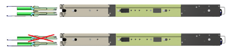
Cable Orientation
In some switch models, the product's package includes cable retainers. It is highly recommended to use them in order to secure the power cables in place.
When installing retainers for the PSUs of the SN3420 switch systems, please adhere to the following instructions:
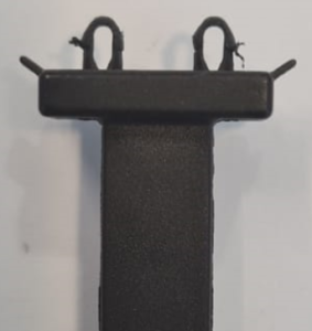
Verify the integrity of the retainer assembly, as demonstrated in the below table:- The snaps' push-pins must have visible edges with no broken or torn parts.
- The shoulders' pins should be in-tact and must not be bent inwards.
Proper Condition
Improper Condition

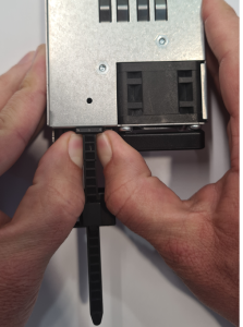
It is advised to place the PSU on a flat, stable surface. While you secure the PSU in place, use two thumbs to insert the retainer's two snaps into the designated holes located near the AC inlet. Make sure that the retainer's plastic loop is facing upwards, as demonstrated in the below table.
NoteFor demonstration purposes, the images in this document show C2P (Connector-to-Power) airflow PSUs with red latches, yet the instructions apply to P2C (Power-to-Connector) PSUs with blue latches as well.
Correct Insertion
Incorrect Insertion
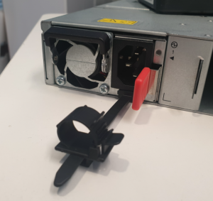
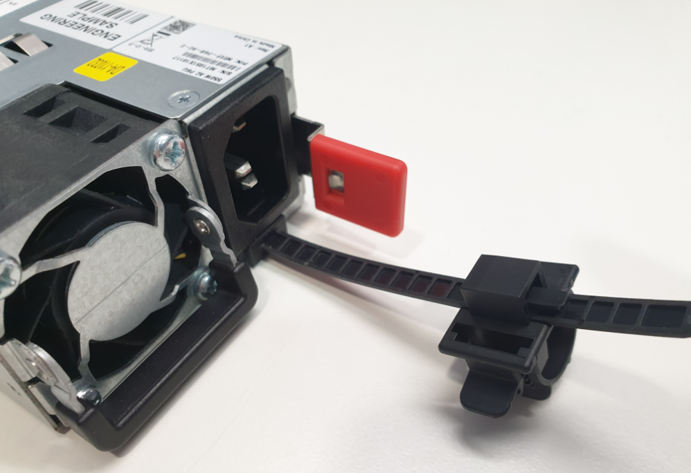
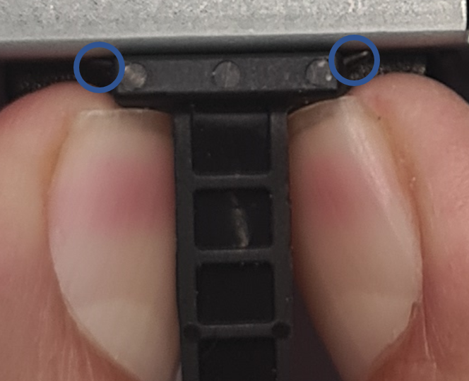
Push the retainer until the shoulders' pins (in blue circles below) are open and aligned with the PSU front panel, as shown in the following table:
Fully Mated Retainer
Make sure that the retainer is fully locked in place by gently attempting to pull it outwards.
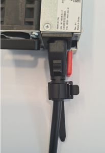
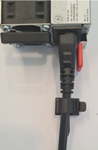
Open the plastic loop and route the AC cord through it. Locate the loop over the AC cord, as shown in the following table, and fasten it tightly.
Proper Loop Placement
Improper Loop Placement
Each cable retainer can be used once only. Once the retainer has been fully inserted and the shoulders' pins have been adjusted, the retainer cannot be used again, and should be discarded if pulled out.
All cables can be inserted or removed with the unit powered on.
To insert a cable, press the connector into the port receptacle until the connector is firmly seated. The LED indicator, corresponding to each data port, will light when the physical connection is established. When a logical connection is made, the relevant port LED will turn on.
To remove a cable, disengage the locks and slowly pull the connector away from the port receptacle. The LED indicator for that port will turn off when the cable is unseated.
For full cabling guidelines, ask your Mellanox representative for a copy of Mellanox Cable Management Guidelines and FAQs Application Note.
For more information about port LEDs, refer to Port LEDs.
Do not force the cable into the cage with more than 40 newtons / 9.0 pounds / 4kg force. Greater insertion force may cause damage to the cable or to the cage.
Cable Orientation
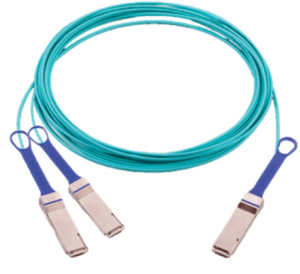
Splitter (Breakout) Cables and Adapters
The breakout option is intended for users planning to run HDR100 using ConnectX-6 only.
The breakout cable is a unique capability, where a single physical quad-lane QSFP port is divided into 2 dual-lane ports. It maximizes flexibility by enabling end users to use a combination of dual-lane and quad-lane interfaces according to the specific requirements of their network. All system ports may be split into 2-lane ports. Splitting a port changes the notation of that port from x/y to x/y/z with “x/y” indicating the previous notation of the port prior to the split and “z” indicating the number of the resulting single-lane port (1,2). Each sub-physical port is then handled as an individual port. For example, splitting port 5 into 2 lanes gives the following new ports: 1/5/1 & 1/5/2. For the systems splitting options, see “QM8700/QM8790 Splitting Options” below.
Sample Breakout Cable
Splitting the interface deletes all configuration on that interface.
This feature is available only for Quantum ASIC systems.
In order to be able to use this feature, the system profile command must be activated with split-ready configuration (cross-reference to system profile command).
For more information on how to change the system’s profile to allow Split-Ready configuration, how to change the module type to a split mode, and how to unsplit a split port, please refer to the "InfiniBand Switching" chapter in the latest MLNX-OS® User Manual.
QM8700/QM8790 Splitting Options
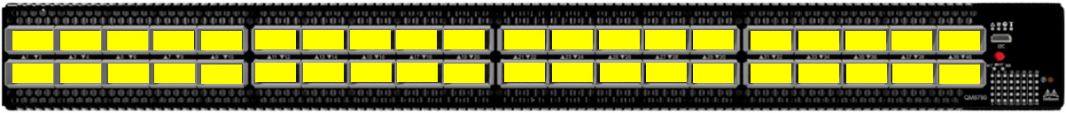
All QSFP56 ports are splittable. Each port can be split to 2xQSFP56 (HDR100) ports. There are no blocking requirements.
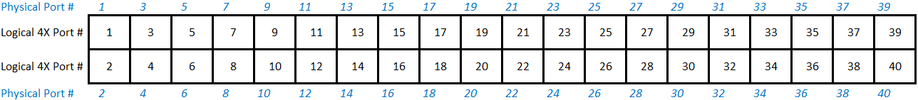
Logical Port Numbering Schematic
Two profiles can be selected for the QM87x0 HDR switch systems. The first one defines the system as a pure 40-port HDR200 switch. The other profile permits any or all QSFP ports to be split into two 2X (HDR100) ports.
The following diagrams attempt to show how the logical ports map onto the physical QSFP ports, as viewed by the IB tools (e.g. ibnetdiscover):
Switch Profile: Non-Splittable (Suitable for L2/Spine Switches)
The IB tools report 41 logical ports. Port 41 is an internal port used for the SHARP Aggregation Node when SHARP is enabled.
Switch Profile: Splittable
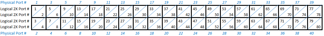
Note: MLNX-OS will use Ethernet port numbering for split QSFP ports. For example, 2X ports 25 and 26 above will be named '1/13/1' and '1/13/2'.
Note: The IB tools will report 81 logical ports. Port 81 is an internal port used for the SHARP Aggregation Node when SHARP is enabled.
When the user wishes to keep a 4X port, rather than splitting it, from the IB tools view, the 4X port receives the odd port number, and the even-numbered port appears as disconnected. For example, if physical Port 13 is not split, in MLNX-OS it will be referred to as '13', and the following scheme will apply:
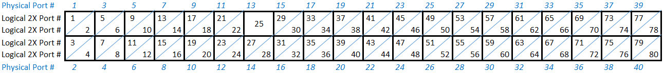
MLNX-OS will refer to this 4X port as '1/13'.