LED Notifications
The system’s LEDs are an important tool for hardware event notification and troubleshooting.
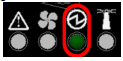
LEDs Symbols
Symbol | Name | Description | Normal Conditions |

| Shows the health of the system. | Green/Flashing green when booting | |

| Shows the health of the fans. | Green | |

| Shows the health of the power supply units. | Green | |

* | Lights up on command through the CLI. | Off or blue when identifying a port |
System Status LED - Front Side
Front Panel | Description |

| The LED in the red oval shows the system’s status. |
It may take up to five minutes to turn on the system. If the System Status LED shows amber after five minutes, unplug the system and call your Mellanox representative for assistance.
System Status LED Assignments
LED Behavior | Description | Action Required |
Solid Green | The system is up and running normally. | N/A |
Flashing Green | The system is booting up. This assignment is valid on managed systems only. | Wait up to five minutes for the end of the booting process. |
Solid Amber | Major error has occurred. For example, corrupted firmware, system is overheated, etc. | If the System Status LED shows amber five minutes after starting the system, unplug the system and call your Mellanox representative for assistance. |
Fan Status LED - Front and Rear Sides
Front Panel | Description | Rear Panel |

| Both of these LEDs in the red ovals show the fans’ status. | 
|
Fan Status Front LED Assignments
LED Behavior | Description | Action Required |
Solid Green | All fans are up and running. | N/A |
Solid Amber | Error, one or more fans are not operating properly. | The faulty FRUs should be replaced. |
Fan Status Rear LED Assignments (One LED per Fan)
LED Behavior | Description | Action Required |
Solid Green | A specific fan unit is operating. | N/A |
Solid Amber | A specific fan unit is missing or not operating properly. | The fan unit should be replaced. |
Risk of Electric Shock! With the fan module removed, power pins are accessible within the module cavity. Do not insert tools or body parts into the fan module cavity.
There are two power supply inlets in the system (for redundancy). The system can operate with only one power supply connected. Each power supply unit has a single 2 color LED that indicates the status of the unit.
Power Status LED
Rear Side Panel

Power Supply Unit Status Front LED Assignments
LED Behavior | Description | Action Required |
Solid Green | All plugged (one or two) power supplies are running normally. | N/A |
Solid Amber | One or both of the power supplies are not operational or not powered up/ the power cord is disconnected. | Make sure the power cord is plugged in and active. If the problem resumes, the FRUs might be faulty, and should then be replaced. |
The power supply status LEDs on the rear side of the system are located on the PSUs themselves. Each PSU has a single 2 color LED.
Power Supply Unit Status Rear LED Assignments
LED Behavior | Description | Action Required |
Solid Green | All PS units are connected and running normally. | N/A |
Flashing Green 1Hz | AC present / Only 12VSB on (PSU off) or PSU in Smart-on state. | Call your Mellanox representative for assistance. |
Amber | AC cord unplugged or AC power lost while the second power supply still has AC input power. | Plug in the AC cord of the faulty PSU. |
PS failure (including voltage out of range and power cord disconnected). | Check voltage. If OK, call your Mellanox representative for assistance. | |
Flashing Amber | Power supply warning events where the power supply continues to operate; high temp, high power, high current, slow fan. | Call your Mellanox representative for assistance. |
Off | No AC power to all power supplies. | Call your Mellanox representative for assistance. |
The UID LED is a debug feature, that the user can use to find a particular system within a cluster by turning on the UID blue LED.
To activate the UID LED on a switch system, run:
switch (config) # led MGMT uid on
To verify the LED status, run:
            switch (config) # show leds
Module LED Status
--------------------------------------------------------------------------
MGMT UID Blues
To deactivate the UID LED on a switch system, run:
switch (config) # led MGMT uid off
By utilizing two pairs of two lanes per port, the systems can support up to 80 ports of 100G. You may switch between the two following states by pressing on the LED Splitting Control button:
Displaying the link status of a single 4-lane port, or of the lower 2-lane split port (if a splitter cable is used). This is the default state.
Displaying the link status of a single 4-lane port, or of the higher 2-lane split port (if a splitter cable is used).
Splitting Indication LEDs

Each time you press on the Lane Select Button, the Port LEDs display will switch to a different state, as follows:
Lane Select Button States
State | Indication LED 1 | Indication LED 2 | Port LEDs Display |
1 | On | Off | 1st 2x |
2 | Off | On | 2nd 2x |
The port LEDs behavior indicates the ports’ state, as follows:
Port LEDs in InfinBand System Mode
LED Behavior | Description | Action Required |
Off | Link is down. | Check the cable. |
Solid Green | Link is up with no traffic. | N/A |
Flashing Green | Link is up with traffic. | N/A |
Solid Amber | Link is up. | Wait for the Logical link to raise. Check that the SM is up. |
Flashing Amber | A problem with the link. | Check that the SM is up. |
In InfiniBand system mode, the LED indicator, corresponding to each data port, will light orange when the physical connection is established (that is, when the unit is powered on and a cable is plugged into the port with the other end of the connector plugged into a functioning port). When a logical connection is made the LED will change to green. When data is being transferred the light will blink green.