Installation
Installation and initialization of the system require attention to the normal mechanical, power, and thermal precautions for rack-mounted equipment.
The rack mounting holes conform to the EIA-310 standard for 19-inch racks. Take precautions to guarantee proper ventilation in order to maintain good airflow at ambient temperature.
This unit is intended for installation in a restricted access location. A restricted access area can be accessed only through the use of a special tool, lock and key, or other means of security.
Unless otherwise specified, NVIDIA products are designed to work in an environmentally controlled data center with low levels of gaseous and dust (particulate) contamination.
The operation environment should meet severity level G1 as per ISA 71.04 for gaseous contamination and ISO 14644-1 class 8 for cleanliness level.
The installation procedure for the system involves the following phases:
|
Step |
Procedure |
See |
|
1 |
Follow the safety warnings |
|
|
2 |
Pay attention to the air flow consideration within the system and rack |
|
|
3 |
Make sure that none of the package contents is missing or damaged |
|
|
4 |
Mount the system into a rack enclosure |
|
|
5 |
Power on the system |
|
|
6 |
Perform system bring-up |
|
|
7 |
[Optional] FRU replacements |
Prior to the installation, please review the Safety Warnings. Note that some warnings may not apply to all models.
NVIDIA systems are offered with two air flow patterns:
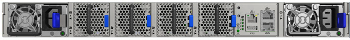
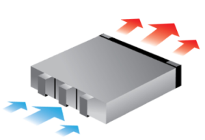
Power (rear) side inlet to connector side outlet - marked with blue power supplies/fans FRUs’ handles.
Air Flow Direction Marking - Power Side Inlet to Connector Side Outlet
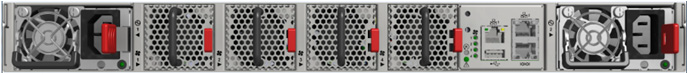
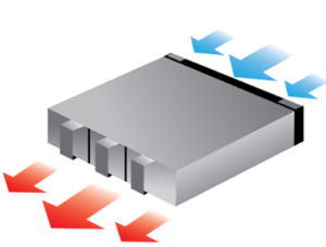
Connector (front) side inlet to power side outlet - marked with red power supplies/fans FRUs’ handles.
Air Flow Direction Marking - Connector Side Inlet to Power Side Outlet
All servers and systems in the same rack should be planned with the same airflow direction.
All FRU components need to have the same air flow direction. A mismatch in the air flow will affect the heat dissipation.
The table below provides an air flow color legend and respective OPN designation.
|
Direction |
Description and OPN Designation |
|
Connector side inlet to power side outlet. Red latches are placed on the power inlet side. |
|
Power side inlet to connector side outlet. Blue latches are placed on the power inlet side. |
Before installing your new system, unpack it and check against the parts list below that all the parts have been sent. Check the parts for visible damage that may have occurred during shipping.
The SB77X0/SB78X0 package content is as follows:
1 x System
1 x Rail kit
2 x Power cables – Type C13-C14
1 x Harness: HAR000911 – Ethernet CAT6A RJ45 to RJ45 2m cable (in SB7X00 models only)
2 x Cable retainers
If anything is damaged or missing, contact your sales representative at Networking-support@nvidia.com.
By default, the system is sold with the static rail kit described in Static Rail Kit.
A telescopic rail-kit can be purchased separately. For the telescopic rail kit installation instructions, see Telescopic Rail Kit.