Multi-Host
This is only applicable to DPUs running on multi-host model.
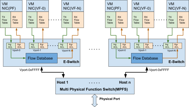
In multi-host mode, each host interface can be divided into up to 4 independent PCIe interfaces. All interfaces would share the same physical port, and are managed by the same multi-physical function switch (MPFS). Each host would have its own e-switch and would control its own traffic.

Similar to Kernel Representors Model, each host here has an uplink representor, PF representor, and VF representors (if SR-IOV is enabled). There are 8 sets of representors (uplink/PF; see example code). For each host to work with OVS offload, the corresponding representors must be added to the OVS bridge.
            139: p0: <BROADCAST,MULTICAST,UP,LOWER_UP> mtu 1500 qdisc mq master ovs-system state UP group default qlen 1000
    link/ether 0c:42:a1:70:1d:b2 brd ff:ff:ff:ff:ff:ff
140: p1: <BROADCAST,MULTICAST,UP,LOWER_UP> mtu 1500 qdisc mq state UP group default qlen 1000
    link/ether 0c:42:a1:70:1d:b3 brd ff:ff:ff:ff:ff:ff
141: p2: <BROADCAST,MULTICAST,UP,LOWER_UP> mtu 1500 qdisc mq master ovs-system state UP group default qlen 1000
    link/ether 0c:42:a1:70:1d:b4 brd ff:ff:ff:ff:ff:ff
142: p3: <BROADCAST,MULTICAST,UP,LOWER_UP> mtu 1500 qdisc mq state UP group default qlen 1000
    link/ether 0c:42:a1:70:1d:b5 brd ff:ff:ff:ff:ff:ff
143: p4: <BROADCAST,MULTICAST,UP,LOWER_UP> mtu 1500 qdisc mq state UP group default qlen 1000
    link/ether 0c:42:a1:70:1d:b6 brd ff:ff:ff:ff:ff:ff
144: p5: <BROADCAST,MULTICAST,UP,LOWER_UP> mtu 1500 qdisc mq state UP group default qlen 1000
    link/ether 0c:42:a1:70:1d:b7 brd ff:ff:ff:ff:ff:ff
145: p6: <BROADCAST,MULTICAST,UP,LOWER_UP> mtu 1500 qdisc mq state UP group default qlen 1000
    link/ether 0c:42:a1:70:1d:b8 brd ff:ff:ff:ff:ff:ff
146: p7: <BROADCAST,MULTICAST,UP,LOWER_UP> mtu 1500 qdisc mq state UP group default qlen 1000
    link/ether 0c:42:a1:70:1d:b9 brd ff:ff:ff:ff:ff:ff
147: pf0hpf: <BROADCAST,MULTICAST,UP,LOWER_UP> mtu 1500 qdisc mq master ovs-system state UP group default qlen 1000
    link/ether 86:c5:8a:b7:7c:84 brd ff:ff:ff:ff:ff:ff
148: pf1hpf: <BROADCAST,MULTICAST,UP,LOWER_UP> mtu 1500 qdisc mq state UP group default qlen 1000
    link/ether 6e:ea:1b:84:88:49 brd ff:ff:ff:ff:ff:ff
149: pf2hpf: <BROADCAST,MULTICAST,UP,LOWER_UP> mtu 1500 qdisc mq state UP group default qlen 1000
    link/ether 92:ec:99:cb:d7:23 brd ff:ff:ff:ff:ff:ff
150: pf3hpf: <BROADCAST,MULTICAST,UP,LOWER_UP> mtu 1500 qdisc mq state UP group default qlen 1000
    link/ether 0e:0d:8e:03:2e:27 brd ff:ff:ff:ff:ff:ff
151: pf4hpf: <BROADCAST,MULTICAST,UP,LOWER_UP> mtu 1500 qdisc mq state UP group default qlen 1000
    link/ether 5e:42:af:05:67:93 brd ff:ff:ff:ff:ff:ff
152: pf5hpf: <BROADCAST,MULTICAST,UP,LOWER_UP> mtu 1500 qdisc mq state UP group default qlen 1000
    link/ether 96:e4:69:4c:b7:7f brd ff:ff:ff:ff:ff:ff
153: pf6hpf: <BROADCAST,MULTICAST,UP,LOWER_UP> mtu 1500 qdisc mq state UP group default qlen 1000
    link/ether 5e:67:33:c0:35:05 brd ff:ff:ff:ff:ff:ff
154: pf7hpf: <BROADCAST,MULTICAST,UP,LOWER_UP> mtu 1500 qdisc mq state UP group default qlen 1000
    link/ether 12:29:7d:56:07:3e brd ff:ff:ff:ff:ff:ff
The following is an example of adding all representors to OVS:
                Bridge armBr-3
        Port armBr-3
            Interface armBr-3
                type: internal
        Port p3
            Interface p3
        Port pf3hpf
            Interface pf3hpf
    Bridge armBr-2
        Port p2
            Interface p2
        Port pf2hpf
            Interface pf2hpf
        Port armBr-2
            Interface armBr-2
                type: internal
    Bridge armBr-5
        Port p5
            Interface p5
        Port pf5hpf
            Interface pf5hpf
        Port armBr-5
            Interface armBr-5
                type: internal
    Bridge armBr-7
        Port pf7hpf
            Interface pf7hpf
        Port armBr-7
            Interface armBr-7
                type: internal
        Port p7
            Interface p7
    Bridge armBr-0
        Port p0
            Interface p0
        Port armBr-0
            Interface armBr-0
                type: internal
        Port pf0hpf
            Interface pf0hpf
    Bridge armBr-4
        Port p4
            Interface p4
        Port pf4hpf
            Interface pf4hpf
        Port armBr-4
            Interface armBr-4
                type: internal
    Bridge armBr-1
        Port armBr-1
            Interface armBr-1
                type: internal
        Port p1
            Interface p1
        Port pf1hpf
            Interface pf1hpf
    Bridge armBr-6
        Port armBr-6
            Interface armBr-6
                type: internal
        Port p6
            Interface p6
        Port pf6hpf
            Interface pf6hpf
    ovs_version: "2.13.1"
For now, users can get the representor-to-host PF mapping by comparing the MAC address queried from host control on the Arm-side and PF MAC on the host-side. In the following example, the user knows p0 is the uplink representor for p6p1 as the MAC address is the same.
From Arm:
            # cat /sys/class/net/p0/smart_nic/pf/config
MAC        : 0c:42:a1:70:1d:9a
MaxTxRate  : 0
State      : Up
From host:
            # ip addr show p6p1
3: p6p1: <BROADCAST,MULTICAST,UP,LOWER_UP> mtu 1500 qdisc mq state UP group default qlen 1000
    link/ether 0c:42:a1:70:1d:9a brd ff:ff:ff:ff:ff:ff
The implicit mapping is as follows:
PF0, PF1 = host controller 1
PF2, PF3 = host controller 2
PF4, PF5 = host controller 3
PF6, PF7 = host controller 4
The maximum SF or VF count across all hosts is limited to 488 in total. The user can divide 488 VFs/SFs to single or multiple controllers as desired.