Fillets
Filleting is an advanced operation that is only available in SMLib (not TSNlib). Filleting is the insertion of a connecting surface, called the fillet surface, between two other surfaces to control the shape of how the two surfaces connect to one another. The common fillet sequence is to replace an existing edge between two surfaces with a new fillet surface and two new rail curves marking where the new fillet surface connects to the original base surfaces. Typically the original surfaces need to be trimmed back to the new rail curves. This trimming operation, along with the creation of the fillet surface, the rail curves, and the modification of the topology connections to make sure that all the pieces are connected together within the Brep model, are all parts of the filleting functionality. Additionally, when working with Brep models, extra care is taken at the ends of the fillets to connect the new fillet geometry (the fillet surface and the rail curves) to the rest of the Brep. The fillet operation manages this by creating special-case fillet end-cap surfaces, edges, and vertices as necessary.
SMLib supports several different kinds of fillet surface shapes to enable several different styles for connecting one surface to another. All but the linear cross section blend of these styles connect the surfaces together smoothly, replacing sharp edges with rounded-smooth edges and corners. The linear cross section blend is used to insert chamfers. These styles include constant radius blends, variable radius blends, circular cross section blends, linear cross section blends (chamfers), and G1, G2 and G3 continuous blends. SMLib filleting has been implemented in a modular fashion making it straightforward to add additional fillet styles, potentially including things like elliptical, parabolic, and cubic blends.
Filleting Framework
SMLib has implemented a filleting framework which handles a wide range of topological cases with a reasonable set of geometric cases. The framework handles the common bookkeeping tasks and has object-oriented handlers to accommodate difficult conditions. Examples of difficult conditions include fillets rolling off the edge of a surface, and fillet rail curves self-intersecting. SMLib implements a basic set of default handlers for each of these conditions. If necessary, end users can change the default behavior by implementing a subclass of the particular handler. For example, if the fillet rolls off the surface, the user might want to change the default behavior of rolling the fillet over onto the adjacent surface to cutting the fillet, rolling a ball along the edge, or just quitting. Users can also implement a subclass handler to change the default behavior of correcting for self-intersecting rail curves
The Filleting Framework supports both Surface-Based Filleting and Topology-Based (or Solid-Based) Filleting. Surface-Based Filleting takes two surfaces and produces a separate fillet surface between them and optionally trims the original surfaces to the new rail curves of the fillet surface. Topology-Based Filleting takes a single Brep and inserts new topology to round edges and corners. Topology-Based Filleting can add fillets to any manifold edge within a solid, open shell, or non-manifold Brep. Because SMLib represents Non-Manifold Topology, SMLib is able to represent results of situations that would normally cause failures in other systems.
SMLib's Filleting Framework is extremely flexible. Adding new functionality to the Framework is the real power of this software. It is designed to make adding seamless extensions as easy as possible. For example, the addition of variable-radius filleting required the implementation of only five methods totaling less than 200 lines of code. Should you decide to extend the Filleting capabilities of SMLib in your system, there are examples to guide you in extending the existing functionality in the Framework. In addition, SMS will be glad to offer you guidance in implementing the extension that you want.
The Filleting Framework also supports a simplified filleting interface that removes most of the complexity for an application to add fillets to Brep models for most typical filleting cases. With a constructor call and two subroutine calls, an application can fillet any selection of edges in a model, with any combination of radius functions and cross section shapes.
This document contains everything you need to know to both utilize existing filleting functionality and to customize the existing functionality to your specific needs. Let us begin by introducing the basic concepts and terminology used in SMLib.
Terminology
The following terms will be used in this document:
Base Surfaces: The two original surfaces that will be joined by the fillet surface.
Fillet Surface: A new surface that is added to the model during the filleting operation.
Filleted Edge, or Edge to be Filleted: The edge of the original Brep to which the fillet is applied. This edge will disappear during filleting, and be replaced with fillet surfaces. One filleted edge is usually replaced by one fillet surface, but it can be more than one, or zero, depending on the radius of the fillet and the surrounding geometry and topology.
Rail Curves: The "long edges" of a fillet surface, which run along the two original faces that meet at the filleted edge. The rail curves are calculated first, before the fillet surface itself, and their intersections with other body topology, and with themselves, largely determine the overall filleting situation.
Fillet Corner: The filleting activity at the vertices of the filleted edges. In topology-based filleting, this will depend on the number of body edges incident at the vertex, which of those are to be filleted, their relative convexity, and how the rail curves intersect with the surrounding topology. New edges and faces can be created at fillet corners.
Cross Section: The shape of the cross section of the fillet surface. This is created after the rail curves are traced out, and is independent of the radius of the fillet. Fillet surfaces typically have a circular cross section for constant and variable radius rolling ball blends or linear cross sections for chamfers, but other shapes are possible.
Using the Filleting Framework
SMLib uses three concepts to specify how to place the rail curves, form the fillet surface shape, and connect the ends of the fillets to the rest of the Brep geometry. These concepts are the radius of the fillet, the fillet surface cross section shape, and the fillet corner generation methodology.
Fillet Solvers: Radius Definition
Surface-Surface filleting in TSNLib supports only constant-radius fillets. Variable-radius fillets are not supported due to the problem of defining a radius function without an existing edge to run the fillet along. Constant-width fillets could be added, but are not implemented at present. TSNlib does support differential offsets however: different radius values may be specified for the two surfaces, resulting in a non-circular blend.
Fillet Surface Generators: Cross Section Shapes
The following cross-section shapes are implemented in TSNlib. Examples of these are pictured in the Figures, below.
- Circular cross section – Rolling-ball Fillet: produces a surface whose cross sections are either an exact rational circle, or an approximation of a circle (SmCircularCrossSectionFSG)
- Linear cross section – Chamfer: produces a surface with a linear cross section. (SmLinearCrossSectionFSG)
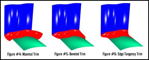
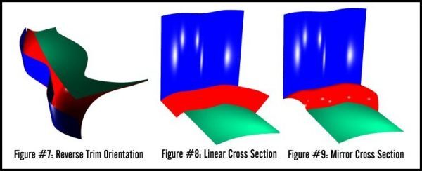
Higher-continuity blend-curve sections have not currently been implemented in surface-surface filleting. TSNLib does support two other variations on the circular cross-section shapes:
- Mirrored: the circular cross section can be "mirrored" across the line between the rail curves. This fillet surface is not tangent to the base surfaces.
- Complementary: the complementary portion of the circular cross section can be used instead of the usual blend section. This fillet surface meets the base surfaces in a cusp.
Radius Definition: The radius definition controls where SMLib generates the shape of the rail curves on the two underlying surfaces of the edge being filleted. These rail curves are used both as the fillet surface bounds and to connect the fillet surface to the original underlying surfaces. Examples of SMLib radius definitions include Constant Radius Rolling Ball, Variable Radius Rolling Ball, and Constant Distance Between Rail Curves. The Radius Definition is implemented in the classes derived from SmFilletSolver.
Cross Section Type: The cross section type controls the cross section shape of the fillet surface between the two rail curves. Examples of SMLib cross section types include Circular Cross Section (Round), Linear Cross Section (Chamfer), and G1, G2 and G3 continuous blends. Other possible cross sections could include elliptical, parabolic, and cubic blends. Cross section shape is implemented in classes derived from SmFilletSurfaceGenerator. Note that the Radius Definition and the fillet surface Cross Section Type are independent and can be mixed and matched in any way.
Fillet Corner Generation: The fillet corner generation methodology specifies what happens at the ends of topological fillets. At vertices where only a single edge is filleted, this specifies how the end of the fillet joins the original Topology. For example, fillets may be extended to intersect adjacent surfaces, or there may be an extension of an adjacent surface to fill a gap. At vertices where more than one edge is filleted, this specifies how the fillets will join each other. For example, fillets may be joined by a Bevel or by a Corner Blend. Fillet corner generation is handled by classes derived from SmFilletCorner. It is generally done automatically by the system.
Fillet Corners
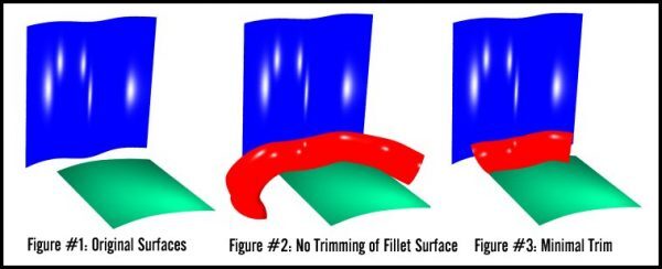
In TSNLib, this describes how the ends of the fillet surface are trimmed. The following options are available:
- No trimming: The fillet surface extends beyond the boundaries of the base surfaces. It is defined on extensions of the base surfaces.
- Minimal Trim: The fillet surface is trimmed to the first intersection with a boundary of one of the base surfaces. This is an isoparametric trim, running straight along the cross section.
- Maximal Trim: The fillet surface is trimmed to the farther intersection with a boundary of one of the base surfaces. This is also an isoparametric trim.
- Beveled Trim: The fillet surface is trimmed at the intersections with the boundaries of both base surfaces. This trim is a straight line in the parameter space of the fillet surface, connecting the two points of intersection.
- Tangency Trim: The fillet surface is trimmed such that its boundaries are tangent to the boundaries of the base surfaces where they intersect.
Filleting Process
The filleting process for Surface-Surface is encapsulated in a single method of SmFilletExecutive called SurfaceSurfaceFillet(). The various parameters for the fillet are passed as arguments, and the method does all of the work required to create the fillet surface. The arguments passed are:
- The two surfaces to be filleted.
- The two radii for the surfaces (generally the same value).
- A tolerance value for the offset-intersection.
- Cross-section type: linear (chamfer), approximate circular, or exact (rational) circular.
- Accuracy of approximate-circular cross section, expressed as a percent of radius.
- How to trim the two ends of the fillet surface.
- How to trim the base surfaces, along the fillet rail.
- Whether to mirror a circular fillet.
- Whether to use the complement of a circular fillet.
If these options are not sufficient for a specific fillet, the user could probably find what is desired by inspecting the source code of SmFilletExecutive::SurfaceSurfaceFillet(). In addition, SMLib will be happy to assist, perhaps adding optional arguments to the method, or adding functionality to surface-surface filleting.
Surface-Based Filleting
Surface Filleting
Perhaps the best way to show you how to use filleting is to walk you through the little filleting application that is in iwfillet_test.cpp. It takes two trimmed surfaces and computes the starting points for the surface fillet solver to use in tracing out the rail curves. It does a relatively good job of computing all possible fillets and finding good starting points by intersecting the offset surfaces to get seed points for the surface fillet solver. It tests offsets in both directions for each surface. In some cases there are multiple correct answers to this problem. To further refine this function, it should take offset directions (positive or negative relative to the surface normal) for each surface.
As you can see there are various tools that need to be put together to make to make surface filleting work. Here is an outline of the process:
- Create a fillet executive object
- For each surface/surface pair to fillet
- Create surface/surface fillet solver
- Create fillet cross section curve generator
- Attach cross section generator to the fillet solver
- Set the trim type of the fillet solver
- Attach the fillet solver to the fillet executive
- Test the resulting Brep to see if any surfaces are produced
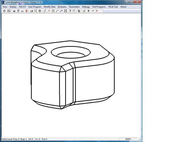
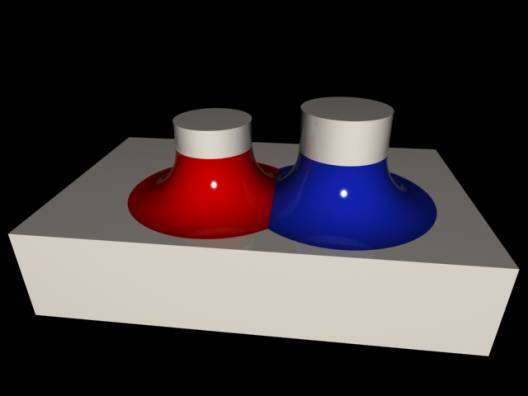
Surface Filleting Figures
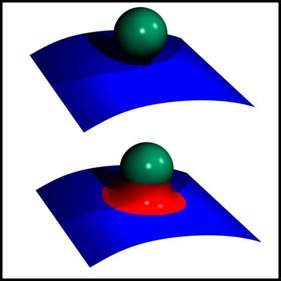
Closed Fillet of Sphere and NURBS
Topology-Based Filleting
Topology-Based Filleting takes as input a single Brep model and modifies that representation to insert fillet topology and geometry. The algorithm is an edge- and vertex-filleting algorithm. You choose edges to fillet and attach Fillet Solvers to the edges. The Fillet Solvers tell the Filleting Framework how the filleting should be done. A default mechanism is used to either blend or bevel the joints between edge fillets that meet at a vertex. It is possible to fillet both solids and open shells.
Filleting Process
Applications can fillet any combination of manifold edges within solid, shell, and non-manifold Breps using either SMLib's simplified filleting interface or by calling filleting class methods directly. The simplified filleting interface should be sufficient for most common filleting operations.
The Simplified Filleting Interface process:
- Create an SmFilletExecutive object
- Call one of the versions of the Fillet Executive's SetFilletParameters() method, to specify the edges to be filleted, the radius and cross section information for each, and tolerances.
- Call the DoFillet() method of the Fillet Executive to perform the filleting operation
The Direct Fillet Class Interface process:
- Create an SmFilletExecutive object
- Specify the tolerances for the filleting
- For each edge to be filleted:
- Create a Fillet Solver of the appropriate sublcass of SmFilletSolver to specify the radius
- Create a Fillet Surface Generator of the appropriate subclass of SmFilletSurfaceGenerator to specify the cross section
- Attach the Fillet Surface Generator to the Fillet Solver
- Load the Fillet Solver into the Fillet Executive
- Call the CreateFilletCorners() method of the Fillet Executive to set up the fillet corners
- Call the DoFilleting() method of the Fillet Executive to perform the filleting operation
There are several examples of using both approaches in SMLib's Examples set, and in the source code.
Status of Topology-Based Filleting
In this section we discuss the current state of the three basics of SMLib filleting: radius definition, cross section shapes, and fillet corners. We also discuss the capabilities of SMLib in the case where the specified radius is too large to fit into a rounded inside corner, or interferes with other topology.
Fillet Solvers: Radius Definition
The first step of topology-based filleting is to define and associate a fillet solver to a manifold edge to specify how to construct the fillet's rail curves. Any manifold edge can be filleted whether that edge is in a manifold, a non-manifold, or shell Brep. Manifold edges are edges connected to exactly two adjacent faces. The three currently implemented fillet solver types that generate rail curves are:
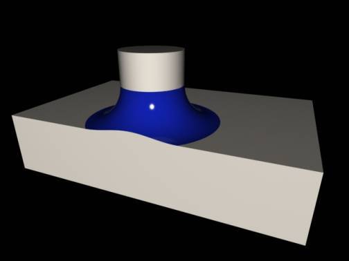
- Constant Radius Rolling Ball: a theoretical sphere of constant radius is rolled along between two surfaces. The points where the ball touches the surfaces defines the rail curves. In some cases the ball may actually roll onto an adjacent surface or onto adjacent edges. (See "Constant Radius" in the Figures below.)
- Variable Radius Rolling Ball: a theoretical sphere that changes radius according to some predefined law is rolled between two surfaces to trace out rail curves. The law is typically defined relative to the edge being filleted. There are several ways to define the radius function. (See "Variable Radius" in the Figures below.) It is possible to have the fillet radius go to zero at one or both ends of the edge.
- Constant Distance Between Rail Curves: a theoretical sphere that changes radius to keep the distance between two rail curves constant is rolled along to trace the rail curves. (See "Constant Distance" in the Figures below.)
Fillet Surface Generators: Cross Section Shapes
The second step of topology-based filleting is to define and associate a fillet surface generator to the edge being filleted. After the edge's fillet solver has been used to define the rail curves, the edge's fillet surface generator is used to specify the shape of the fillet surface that fills in the space between the two rail curves. The following fillet surface generation techniques have been implemented:
- Circular cross section – Rolling-ball Fillet: produces a surface whose cross sections are either an exact rational circle, or an approximation of a circle (SmCircularCrossSectionFSG)
- Linear cross section – Chamfer: produces a surface with a linear cross section. (SmLinearCrossSectionFSG)
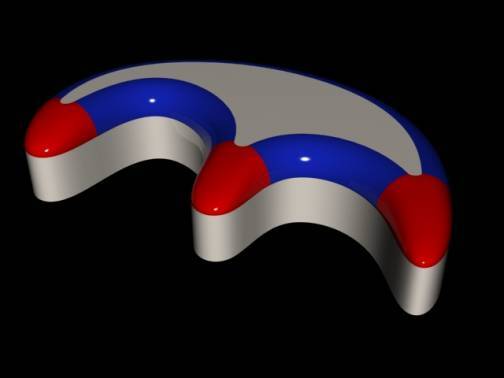
- Higher-continuity blend-curve section: produces a surface that meets the base surfaces with G1, G2, or G3 continuity across the rail curves. The actual fillet surface cross section shapes are created by skinning the rail curve boundary constraints. (SmBlendCurveCrossSectionFSG)
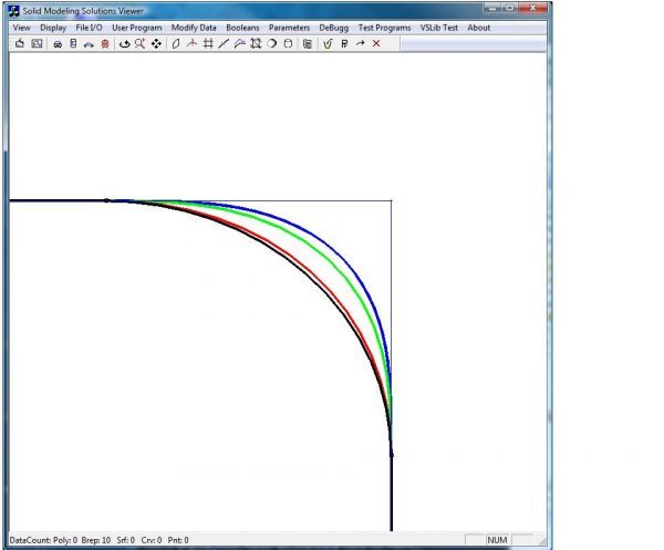
Cross section shapes: Circular (black); G1 continuity (red); G2 (green); G3 (blue)
Fillet Corners
The final step of topology-based filleting is to define and associate a fillet corner object (SmFilletCorner) to every vertex attached to an edge being filleted. This controls how the edge fillets get connected to pre-existing and other newly created fillet geometry. SMLib automatically selects the type of fillet corner object to associate with each vertex depending on the number of edges connected to the vertex and the relative convexities of those edges.
SMLib uses the following notation: a fillet corner where N total edges are incident, and M of them are to be filleted, is denoted an NxM corner. The following fillet corner cases have been implemented:
- Nx1 Closed Corner (SmFilletNx1ClosedCorner) Denotes a case where the edge to be filleted is a closed edge (i.e. top edge of a cylinder) that attaches to the vertex two times. It can have either zero or one additional edges coming into the vertex. If the edge meets itself tangentially (as with a cylinder), the fillet surface will be closed and joined without any trimming. In the non-tangent case (e.g., teardrop shape, extruded), the fillet surface is split in the middle, and the pieces are intersected where they meet.
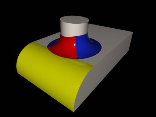
- 3x1 Corner (SmFilletNx1Corner) Denotes a case where there are 3 edges adjacent to a vertex and one of them needs to be filleted. There are three cases here, depending on the relative convexity of the three edges, and which edge is to be filleted.
- If all three edges have the same convexity ("univex"), the rail curves intersect nicely with the adjacent Brep edges, and the fillet surface intersects with the untrimmed end face. The end face will be trimmed back to the fillet surface.
- If one of the three edges has the opposite convexity to the other two ("mixed convexity"), and the filleted edge is the one with opposite convexity, then the rail curves will still intersect nicely with the adjacent Brep edges, but the end face must be extended to be intersected with the fillet surface. The end face will be extended out to the fillet surface.
- In the mixed-convexity case where the filleted edge is one of the two with the same convexity, then one of the rail curves will not intersect with the adjacent Brep edge; that edge must be extended to intersect the rail curve. Again, the end face must be extended to be intersected with the fillet surface, and will be extended out to the fillet surface.
- 3x2 Corner (SmFilletNx2Corner) Denotes a case where three edges are adjacent to a vertex and two of them are to be filleted.
- If the filleted edges are tangent at the vertex and have the same radius and cross section, the fillet surfaces will be joined tangentially without any trimming or intersection. (If they have a different radius or cross section, they cannot be filleted.)
- At a univex corner (all edges with same convexity), adjacent rail curves will intersect each other, the other two rail curves will intersect body edges, and the fillet surfaces will intersect each other. In this case the fillet surfaces will be intersected and a bevel created.
- At a mixed-convexity corner where the two filleted edges have opposite convexities, adjacent rail curves will intersect, the fillet surfaces will intersect, and a corner patch will be created.
- At a mixed-convexity corner where the two filleted edges have the same convexities, the rail curves that are in the same face must be extended and/or blended to meet. A corner patch will also be created.
- NxN Same-Convexity Corner (SmFilletConvexNxNCorner) Denotes a case where all edges adjacent to a vertex are to be filleted and all of the rail curves intersect. This case will create a 3, 4 or N-sided tangential corner blend between all of the adjacent fillet surfaces. In some cases the corner will be an analytical surface (Sphere). In the N-sided corner case, when N > 3, multiple four-sided patches will be created to fill the corner. It is also possible to utilize this corner to produce a beveled case instead of a blend by setting the SetBevelFlag to TRUE for the corner.
- NxN Mixed-Convexity Corner (SmFilletConcaveNxNCorner) Denotes a case where all edges adjacent to a vertex are to be filleted and not all of the rail curves intersect. In this case a blend curve will be made between the rail curves on the given face. The tangential corner blend will then be made between adjacent fillet surfaces and the blend curves. In some cases the corner will be an analytical surface (Torus).
- Open Shell Corner (SmFilletOpenCorner) Denotes a case where there is no ending face. Two of the edges are lamina edges and the edge to be filleted is the only manifold edge at the vertex. The fillet will be trimmed by a line in the parameter space of the fillet surface between the vertices.
- Tangent Surface Corner A corner where the faces adjacent to the filleted edge become tangent. The fillet surface becomes degenerate where the adjacent faces become tangent. See the Figure entitled "Disappearing Fillets with Tangent Faces".
- Degenerate Rail Fillets The case where one of the rail curves degenerates to a point. An example of this would be filleting the top of a cylinder with a radius the same as the cylinder.
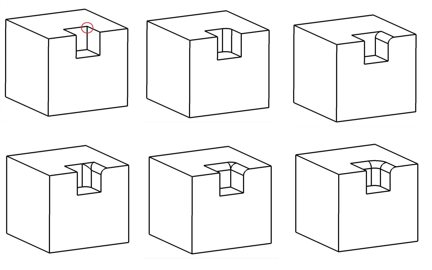
Examples of 3xN fillets at a mixed-convexity corner. Note the extensions of body faces and edges in some cases. A 3x3 (NxN) case is pictured for completeness.
Example: Chamfer, and NxN corners, same- and mixed-convexity cases.
Large Radius Filleting
Standard filleting algorithms assume that the size of the fillet is relatively small compared to the size of the features of the object being filleting. For example, they assume that the radius of the fillet is smaller than the radius of curvature of the surfaces of the edge being filleted. They also assume that the rail curves of a fillet surface do not intersect interior features of the face, and that they do intersect the adjacent topological edges at each vertex. These assumptions make the implementation of filleting easier, but they do not cover an adequate number of cases required by real-world engineering problems. Therefore SMLib has algorithms to handle large-radius situations. SMLib's large-radius capabilities in the Filleting Framework include:
- Self-Intersecting Rail Curves: If the rail curves of a fillet self-intersect, this generally means that the radius of the fillet is larger than that of one of the original base surfaces. In this case, the fillet is trimmed back from intersection and a blend surface is inserted. See the results in the Figure "Self-Intersecting Rail Curves", below.
- Small Adjacent Edges: If the rail curve fails to intersect the adjacent edge at a vertex of the edge to be filleted, SMLib utilizes classification to determine the intersection.
- Rail Curves Intersecting Features: this occurs when a fillet rail curve intersects any edge of the original body other than the one that is adjacent at the vertex. There are several classes of this problem, which are pictured below.
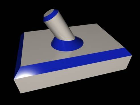
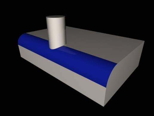
- Tangent Surface Rollover: fillet rolls onto another surface which is tangent to base surface.
- Cliff Rollover: fillet rolls off the edge of a cliff and gets trimmed by an extension of the cliff face.
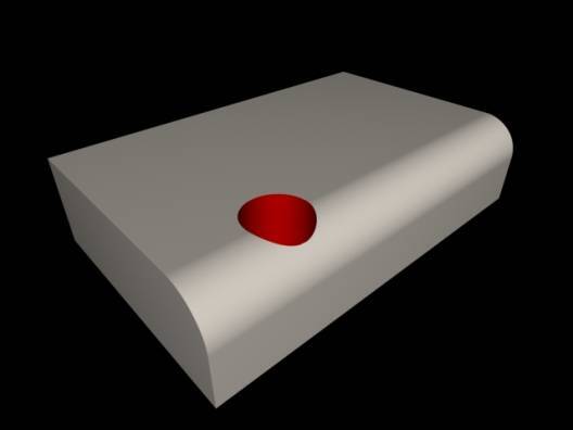
- Positive Fillet/Positive Feature: a positive fillet rolls into positive object like a Boss – fillet is created and flows around the boss.
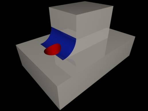
- Negative Fillet/Negative Feature: fillet cuts away part of an interior negative feature like a hole in a box near the edge.
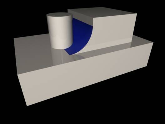
- Negative Fillet/Positive Feature Interaction: a negative fillet runs into a positive feature and the positive feature gets extended down to meet the fillet surface.
- Positive Fillet/Negative Feature Interaction: fillet rolls over a hole the hole surface gets extended and the fillet gets trimmed just like the Cliff Rollover.
- Fillet/Fillet Intersection: two fillets applied during the same operation intersect each other – intersection computed and trimming applied to produce a valid solid.
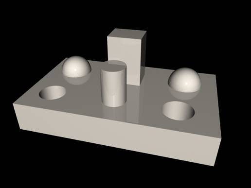
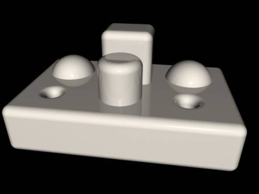
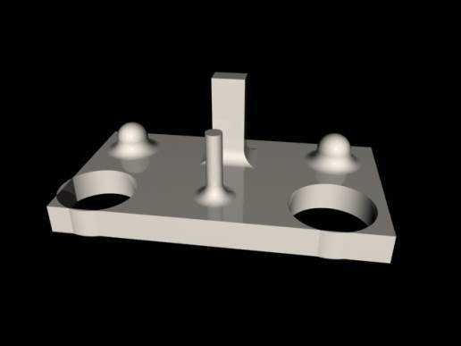
Topology-Based Filleting Figures
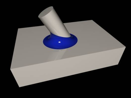
Constant Radius
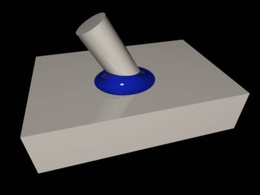
Constant Distance
Variable Radius
Linear Cross section
Self Intersecting Rail Curves
Cliff Rollover
Tangent Surface Rollover
Negative Fillet/Negative Feature
Negative Fillet/Positive Feature
Positive Fillet/Negative Feature
Positive Fillet/Positive Feature
Fillet/Fillet Intersections
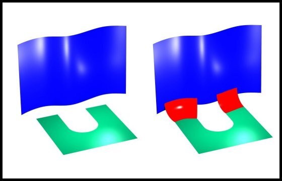
Filleting used in Offsetting: Original Solid
Offset Solid/Positive Offset
Offset Solid/Negative Offset
Shelled Solid

| 
| ||

|
|


|
| 
| ||
|
|
| ||

| 
| ||

| 
| ||

|

Submitting a Filleting Bug
This could be a difficult task if you have added substantial functionality using the customization features. In that case you may have to ship us some software to test along with model geometry.
For the current time and utilization of trimmed surface filleting the best thing to do is to dump out the two original Breps and send us the information used to generate the surface fillet (radius, surface orientations, tolerances, guess points, etc.). Optionally if you have created a high level function like the example given above, you should also send us that to utilize with the corresponding arguments. If the arguments are complex, it might be easier to write them to a Fillet Definition File.