Topology
Introduction
SMLib provides high level topological operations: Solid Booleans, Merge, Make-Manifold, Topology-Based Filleting, Tessellation, Shell Offset, and Feature Removal.
Non-Manifold Topology
This is an introduction to SMLib Geometric Objects, and how the various pieces of geometry are put together. The relationships between the objects is the topology and SMLib topology is similar to that of other systems. This provides a general understanding that will apply to many geometric modeling systems.
When a closed curve lies on a surface, it can be used to trim the surface to that boundary curve and this results in a trimmed surface. If two surfaces share the same segment of a boundary, this is called an edge and the two surfaces are neighbors. If we have a way to keep track of which surfaces share an edge, we have added a topology to our modeling system.
A trimmed surface, together with the information about its neighbors is referred to as a face. A face must have an outer boundary and it may have many inner boundaries or “holes”. When two faces are joined along an edge, the result is then referred to as a shell. A shell is just a set of two or more connected faces.
If a shell is closed then you have a solid. A solid has an outer closed shell and possibly many inner shells that define cavities in the solid. A “region” encloses space from a closed outer shell or between two closed shells (one inside the other) and has volume. The outer region is the infinite region, so a closed box is represented by two regions – the outer infinite region, and the region within the box. If there is a box within the box ( a ‘thick’ box) then there are 3 regions. The inner box may ‘float in space’ without being attached to the outer box….it may not be physically possible, but it is topologically acceptable.
In a closed solid, each boundary has edges which are shared by two neighboring faces, so this is referred to as a boundary representation or “Brep”. The first implementations of a Brep model were Manifold, that is. …they allowed for only two faces to share an edge, hence the name “twin-edge boundary representation”….or brep. If more than two faces can share an Edge, the topology is Non-Manifold.
It turns out that the manifold restriction that an edge may have only two neighbors is very limiting. Any time you intersect two surfaces, if you look in the neighborhood of a point on the intersection curve, there appear to be four neighboring surfaces at that point. That’s what is meant by being “non-manifold”. A manifold edge is restricted to having two neighboring surfaces and a non-manifold edge may have more than two surfaces that share that edge.
Each boundary of a face consists of a closed loop of edges. In the topology structure each loop has a list of edges, and the same edge may be used by two or more faces and that’s what “EdgeUse” refers to. The term edgeuse has real importance since there could be many uses of an edge.
If we construct a box (it defines a region) and then if we add another box right next to it, we have another region. Since they share the same face, you can see why we need to have “FaceUses”. The face is used on one region, and the face is also used in the other region.
There are many methods for extracting topological information that defines a Brep. Down to the FaceUse level, the various methods include:
- SmBrep::GetRegions() – Returns the list of regions with the first region being the infinite region
- SmBrep::GetInfiniteRegion() – May be used to determine which region is the infinite one.
- SmRegion::GetShells() – Returns the list of shells for this region.
- SmShell::GetFaceuses() – Returns the list of faceuses that define this shell.
- SmFaceuse::GetOtherFaceuse() – Returns the faceuse on the other side of this face which will allow us to find which region is next to the original faceuse.
To get to the region from a faceuse you use:
- SmFaceuse::GetShell() …..then
- SmShell::GetRegion()
Brep – Boundary Representation
The SMLib Brep model is an instance of a modeling structure called the radial edge structure.
The pieces of the SMLib Brep model include shapes, topology objects, and special connectivity objects called “uses.”
The key idea of Brep modeling is that simple trimmed-shapes connect together through their boundaries to form complex geometry models just as a set of small glass pieces welded together along their edges form a stain glass window.
Shapes are points, curves, and surfaces each of which is a simply connected point set within a 3D space. Shapes can be infinite (planes, cylinders, lines and such) or finite (Bspline curves and surfaces) but have no sense of boundaries. For every shape there is a simple topology object that adds trimming to the shape so that it can be connected into a Brep model. The SMLib simple topology objects are vertices, edges, faces, and regions. Important combinations of simple topology objects forming key boundaries within a geometry model are also represented explicitly; a loop is any closed sequence of connected edges used to bound a face and a shell is any set of faces connected edge-to-edge to bound a region.
We say that a topology object is “used” each time it connects to the geometry model to form a boundary. In general, all of the SMLib simple topology objects participate in a hierarchy of boundaries: regions are bounded by faces (gathered into connected shells), faces are bounded by edges (gathered into connected loops), and edges are bounded by vertices.
Boundaries are used to establish neighbor relations. Topology objects don’t connect directly to their neighbors; rather neighbor relationships are created when two topology objects both use a common boundary.
A geometry model represented as a hierarchy of boundary connections is referred to as a boundary representation or “Brep” model.
In SMLib, each use of a topology object (that can be used more than one time in one model) is represented by a specialized use object. Each use of a face to bound a region is represented by a Faceuse. Each use of a loop to bound a face is represented by a Loopuse. Each use of an edge to bound a face is represented by an Edgeuse, and each use of a vertex to bound an edge is represented by a Vertexuse. There are no Shelluse objects because shells are used just once per model to bound one region and the shell object can act as its own Shelluse object.
In SMLib, a connection between an object and a boundary is represented as a connection between their use objects.
The following diagram shows the SMLib Brep object model.
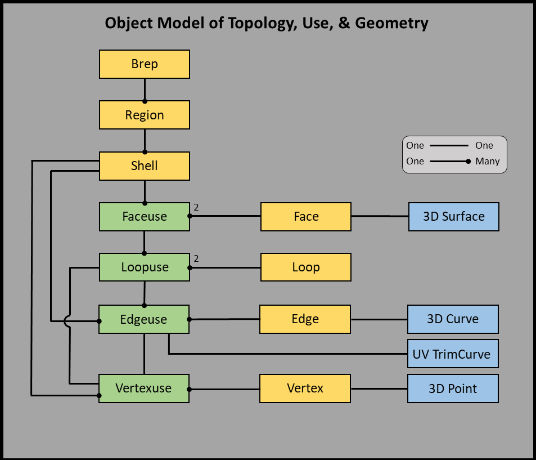
The Brep Object
Now we need to explain some of the details of the SMLib Brep object that is shown in the diagram above. The figures that follow will help us understand how FaceUse, LoopUse, EdgeUse and VertexUse are used in the radial edge structure.
Faces and FaceUses
Within the SMLib Brep, faces are two sided; each side of a face is represented by a Faceuse and each Faceuse (acting as part of a shell) is used to bound one region. The two Faceuses representing the two sides of a single face are called “mates”.
Each Faceuse is contained in just one Shell.
Each Shell has one pointer to its first Faceuse. The first Faceuse has no special significance.
Each Faceuse has a pointer to its owning shell and a doubly linked-list of other Faceuses owned by that shell.
Each Faceuse has a pointer to its owning face.
Each Face has a pointer to a 3D surface, which defines its 3D shape.
The following diagram represents the connections found between topology objects contained in one Faceuse pointer that has two Loopuses.
This represents the topological information used for one Faceuse on one side of a Face. We are looking at this face from inside the region that this Faceuse bounds. The other side of the face sitting on the other side of this image is not displayed. It is associated with a second Faceuse that contains a mirrored set of all the mate Loopuses, Edgeuses, and Vertexuses shown for this Faceuse. If it were shown, we would be looking at that 2nd Faceuse from a point outside of its region located on the other side of this image.
Note that the Edgeuse only points to one Vertexuse, yet an Edge is (usually) connected to two vertices, one at the start and one at the end. To get both vertices attached to one edge walk the Edgeuse’s mate pointer as:
SmVertex *pV1 = pEdge->GetPrimaryEdgeUse()->GetVertexUse()->GetVertex();
SmVertex *pV2 = pEdge->GetPrimaryEdgeUse()->GetMate()->GetVertexUse()->GetVertex();
Shells and Regions
Shells are one sided and are used just once to bound one region. A shell is a set of connected Faceuses all bounding a common region. A region is always bounded by one outer shell defining its overall extent and bounded by any number of inner shells each representing a cavity within the region. There is one special region called the infinite-region that models all space outside of the current model. That one region is an exception in that it has no outer shell, but it may have any number of inner shells marking the distinct pieces of the Brep model as cavities within infinite space.
When a shell is closed it divides all of space into two regions, inside and out. In SMLib a shell is only connected to its inner region and does not pay attention to outer regions. All of the shells of one region, including the outer shell and all the inner shells, treat that region as their inside region.
For models containing only simply closed shells, the two Faceuses of one face will be contained in different shells. For models with open shells, it is possible to create a face whose two Faceuses are contained in just one shell.
Each region points to one shell that is its first outer shell.
Each shell has a pointer to its owning region and a doubly linked list of other shells owned by that region. The first shell on this list is always the outer shell, the rest are inner shells.
You can pass over to an adjacent shell by moving across a face with the pFaceUse->m_pFUMate Faceuse pointers.
Loops and LoopUses
Faces are bounded by loops. A loop is a closed sequence of connected Edgeuses all bounding a common Faceuse. Loops, like shells, are one sided and bound just one face. A face is always bounded by one outer loop defining its overall extent and bounded by any number of inner loops each representing a hole within the face. Unlike shells Loops are always closed, they are never open. Every Faceuse must have one outer boundary, which is sometimes just the surface boundary edges. SMLib does not allow outer-boundaries to be nested within an inner boundary – in that case it would form a new face.
Since faces are used twice, each loop is also used twice to bound both sides of the face. In SMLib, the actual connection between a face and a loop is made between the Faceuse and the Loopuse.
One could imagine a face that had different loops on each of its two sides, but in SMLib every loop on a face is represented equally on both sides of the face.
Each Loop has one pointer to its primary Loopuse.
Each Faceuse has a pointer to its first outer loop.
Each Loopuse has a pointer to its owning Loop and to its mate.
Each Loopuse also has a pointer to its owning Faceuse and a doubly linked list to other Loopuses owned by the same Faceuse. The first Loopuse on this list is always the Faceuse’s outer loop and all other Loopuses on this list are inner loops.
The FaceUse points to EdgeUses, not VertexUses. An EdgeUse only points to one VertexUse, yet an Edge has (usually) two vertices, one at the start and one at the end. In order to get the Vertex at one end of an Edge, we get the primary EdgeUse for the Edge, get its VertexUse, and get its Vertex:
SmVertex *pV1 = pEdge->GetPrimaryEdgeUse()->GetVertexUse()->GetVertex();
To get the other Vertex , we use the mate of the EdgeUse, which is the corresponding oppositely-oriented edge on the other side of the face to provide the VertexUse:
SmVertex *pV2 = pEdge->GetPrimaryEdgeUse()->GetMate()->GetVertexUse()->GetVertex();
Edges and EdgeUses
Edges can be thought of as multi-sided; they may be used to bound any number of faces like a book’s spine can bound any number of pages. Each use of an edge (acting as part of a loop) bounds one face. Since faces are two-sided one could again image an edge that bounds only one side of a face and not the other. But in SMLib an edge bounding a face always bounds both sides of that face. So a pair of Edgeuse objects is created every time an edge is used to bound a face. Each Edgeuse is a member of just one Loopuse. The two Edgeuses lie on opposite sides of the face they are bounding, and are called mates. The connection between a face and its edge is represented in SMLib as a pair of connections between the face’s two Faceuses and the edge’s two Edgeuses.
Edgeuses connect together in two different interesting ways; one is to store the radial/mate information about what faces use this edge (see Radial Edges, below); the other is to store the order of edges ( CW or CCW) that form a Loop boundary (outer or inner) within a face.
Edges themselves are bounded by vertices. An edge is always bounded by two vertices. Edges are always simply connected; there is no concept of a hole in an edge. An edge with a hole is modeled in SMLib as two unconnected edges.
An edge can be open or closed. A closed edge is one where the last point of the edge is the same as the first point of the edge. For closed edges, the start vertex equals the end vertex.
Edges are classified according to how many faces to which they attach.
- An edge connected to no faces is called a wire.
- An edge connected to just one face is called a lamina edge.
- An edge connected to just two faces is called a manifold edge.
- An edge connected to more than two faces is called a non-manifold edge.
Each Loopuse will point to its first Edgeuse – which has no special significance.Each Edgeuse points to its owning Loopuse and has a circular doubly linked list of (CCW and CW) connected Edgeuses all owned by the same Loopuse. The Edgeuse is connected to a face through the Loopuse owner.
Each Edgeuse also has a pointer to its owning edge and has a 2nd circular doubly link list of (radial and mate) connected Edgeuses all owned by the same edge.
Each Edge has a pointer to a 3D curve representing its 3D shape.
Each Edgeuse has a pointer to a Trimcurve used to bound its face’s 3D surface.
Note: A manifold modeler assumes every edge will be connected to exactly two faces. The SMLib non-manifold modeler allows any number of faces (from 0 to really large numbers) to be connected to one edge. This difference allows SMLib to model mixed wireframe, surface, manifold, and non-manifold models in one single modeling environment.
Trimmed Surfaces and Trim Curves
Every Edgeuse has one 2D Trimcurve that marks the bound of the edge’s 3D curve in the domain space of the face’s 3D surface. Trimcurves turn a surface into a trimmed-surface by dividing a surface into used and unused portions (when rendering a geometry model only the used portions of a trimmed-surface are displayed). Internally, to save space, a Trimcurve is stored just once for every Edgeuse mate pair to prevent storing unnecessary Trimcurve copies
An Edgeuse’s Trimcurve is computed as the projection of an edge’s 3D curve onto a face’s 3D surface. In SMLib all Trimcurves are represented by 2D Bsplines and care is taken to ensure that the Trimcurve is parameterized in the same manner as the Edge’s 3D curve. So, to within tolerance, the point generated by evaluating the Edge’s 3D curve for a given parameter, will be the same point generated by evaluating the face’s 3D surface at a 2D point found by evaluating the 2D Trimcurve for the common parameter.
Radial Edges
In non-manifold modeling, an Edge may be shared by many different Faces. As a result, it is necessary that we maintain this information in the form of a list of EdgeUses for each Edge. This list of EdgeUses is ordered since it is critical to know the relationship between the Faces that share the same Edge. An Edge together with the ordering of the Faces that share the Edge is referred to as a Radial Edge and it is one of the most important features of this representation.
This figure shows the radial/mate Edgeuses relationships for one edge shared by two faces.
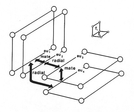
Here one edge connects to both Face1 and Face2. Face1 and Face2 both have two sides making for 4 Faceuses in total. Each Faceuse is bound by one Edgeuse making for 4 Edgeuses as shown surrounding the Edge between Face1 and Face2. These 4 Edgeuses are connected in a circular sequence of radial and mate relationships.
Note that the 2 EdgeUses of Face1 are associated with each other as Mate so given any EdgeUse
EdgeUse::GetMate()
returns the EdgeUse on the other side of the Face.
EdgeUse2 (eu2) of Face1 and EdgeUse3 (eu3) of Face2 are associated to each other as Radial so given any EdgeUse
EdgeUse::GetRadial()
returns the EdgeUse on the neighboring Face.
The real power of this representation is shown by the case where 3 Faces share the same Edge.
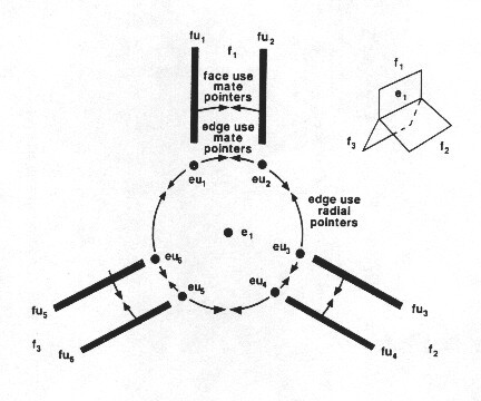
Now we see why we needed to introduce FaceUses, LoopUses and EdgeUses. The relationship between all the Faces that share this Edge is now available. Starting with EdgeUse1 (eu1) if we go Mate, Radial, Mate, Radial, Mate, Radial we are back at EdgeUse1.
Note that a single next/previous value in the EdgeUse is used for both the Mate and the Radial pointers. For each EdgeUse either (the next is the radial, and the previous is the mate) OR (the next is the mate, and the previous is the radial). Which of these two applies depends on the Orientation – if it is the same as the primary edgeuse orientation, then the ‘next’ is the mate.
SmEdgeUse::GetMate(){
SmEdge *pE = pEdgeUse->GetEdge();
SmEdgeuse *pPrimEU = pE->GetPrimaryEdgeuse();
if (pPrimEU->GetOrientation() == pEdgeUse->GetOrientation())
pRet = (SmEdgeuse*) (pEdgeUse->GetNext());
else
pRet = (SmEdgeuse*) (pEdgeUse->GetLast);
}
SmEdgeUse::GetRadial() is as above with next/last interchanged.
Vertices and Vertex Uses
Vertices, like faces and edges, are also multi-sided in that they can be used to bound any number of edges. One Vertexuse object is created each time a vertex is used to bound an edge. The connection between a vertex and an edge is made between the Vertexuse and the Edgeuse. Edgeuses always come in pairs to match the two sides of a face and it would seem that each connection between a vertex and an edge would require two Vertexuses. In the SMLib internals the number of actual Vertexuses is cut in half by only recording a connection between one Vertexuse and one Edgeuse for each vertex-edge connection. The second connection is deduced when needed at run time by examining the Edgeuse mate relationships.
The next figure shows the case of 5 Edgeuses starting at one vertex.
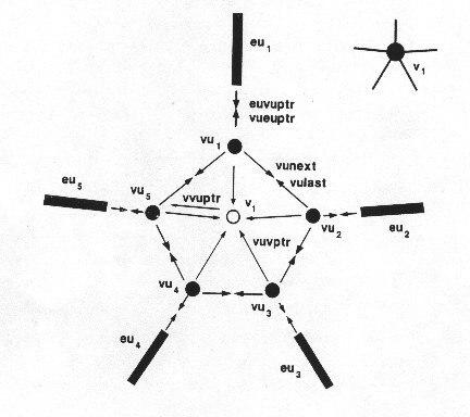
This situation shown in this figure can arise as a planar model in which 5 different faces connect to one vertex through 5 different edges, or it can be thought of, like the last image, as a single vertex attached to one edge that is connected to five different faces oriented so that we see the edge and faces end-on.
In both cases, either 1 edge used 5 times, or 5 edges used 1 time, a total of 10 Edgeuses are bound by this vertex, 5 starting there and 5 ending there. In the figure only those Edgeuses that start at this vertex are shown. The Vertex points to one of the Vertexuses. Each of the Vertexuses points to its owning vertex, to the next and last Vertexuses in the doubly linked list of Vertexuses owned by this vertex, and to an Edgeuse that starts at this vertex.
Walking The Topology Model
There is a set of methods for extracting all of the topological information that defines a Brep. Down to the Faceuse level, the various methods include:
- SmBrep::GetRegions() – Returns the list of regions with one region being the infinite region
- SmBrep::GetInfiniteRegion() – May be used to determine which region is the infinite one
- SmRegion::GetShells() – Returns the list of shells for this region
- SmShell::GetFaceuses() – Returns the list of faceuses that define this shell
- SmFaceuse::GetOtherFaceuse() – Returns the faceuse on the other side of this face and from this other faceuse you are able to determine which region is next to the original faceuse
To get to the region from a Faceuse you use:
- SmFaceuse::GetShell() …..then
- SmShell::GetRegion().
Orientation
In SMLib, all curves and surfaces are represented by parametric functions. Each curve and surface inherits from its function a natural orientation. The parametric functions for curves and surfaces can be written as:
C(t) = [x(t), y(t), z(t)] ; t_min <= t <= t_max
S(u,v) = [x(u,v), y(u,v), z(u,v)]; u_min <= u <= u_max, v_min <= v <= v_max.
Curves get a direction having a beginning that maps to the curve’s smallest parameter value and an end that maps to its largest parameter value. An observer walking along the length of a curve is moving in the positive direction when walking in direction of increasing parameters. At any point, the curve’s 1st derivative, d(C(t))/dt, points in the curve’s positive direction.
Surfaces get an upward and downward side defined by the parametric surface’s oriented surface normal as,
surface normal = (d(S(u,v))/du x d(S(u,v))/dv).
At any point on the surface, the surface normal points to the surface’s upward side and away from surface’s downward side. An observer located some distance away from a surface at the end of the positive surface normal would be looking back at the upward surface.
Faceuse Orientation
A Face has an upward Faceuse and a downward Faceuse. Each Faceuse has a normal direction that points into the region that it bounds. The upward Faceuse’s normal direction is the SAME as that of Face’s Surface Normal. The downward Faceuse’s normal direction is the OPPOSITE direction.
In SMLib, the primary Faceuse pointer stored on a Face is always the upward Faceuse.
The upward Faceuse’s mate is always a Downward Faceuse. Each Faceuse stores an orientation bit whose values is always SM_OT_SAME for upward Faceuses and SM_OT_OPPOSITE for downward Faceuses.
Loop Orientation
Each Loop stores two Loopuse orientations, one connected to each to the two Faceuses of the face being bounded. By convention the primary Loopuse is always connected to the Face’s primary upward Faceuse. The primary Loopuse’s mate is always connected to the downward Faceuse stored as the primary Faceuse’s mate.
Loopuse Orientation
Inner and outer Loopuses have different orientations. Each Loopuse stores an orientation bit whose value is always SM_OT_SAME for outer loops and SM_OT_SAME for inner loops.
In an outer Loopuse, an observer positioned to look down a Faceuse’s normal watching a point traverse the Loopuse’s Edgeuses from start to end, will see that point move in a counter-clockwise cycle. The same observer watching a point traverse an inner Loopuse will see that point moving in a clockwise cycle.
Edgeuse Orientation
Every Edgeuse has a direction that marks its beginning and ending vertices and marks which side of the Faceuse it bounds is inside or out. Each Edgeuse stores an orientation bit that is set to SM_TO_SAME when the Edgeuse orientation is the same as the Edge’s curve orientation, and SM_TO_OPPOSITE when the Edgeuse’s orientation opposes the curve orientation.
LEFT-HAND RULE: The orientation of each Edgeuse is set so that each Edgeuse divides its owning Faceuse into an inside and an outside. The rule is that an observer moving in the positive direction along the length of the Edgeuse and oriented in the same direction as the owning Faceuse’s normal will always have the inside of the face on his left hand side. This rule defines a bi-normal vector that always points towards the interior of the face for every point on an Edgeuse.
Bi-normal = cross_product(Faceuse_Normal, Edgeuse_direction).
RADIAL/MATE Edgeuse Orientations: A pair of mate Edgeuses will always have opposite orientations to one another. Similarly every pair of radial Edgeuses also have opposite orientations to one another. The primary Edgeuse pointed to by an Edge can be oriented in either direction.
CCW/CW or NEXT/LAST Edgeuse Orientations: The doubly linked list of Edgeuses used to store all the Edgeuses contained in one Loopuse are stored in a pair of pointers called CCW_Edgeuse and CW_Edgeuse. These names are a bit confusing but the pointers are used consistently.
The CCW_Edgeuse pointer always connects the end of this Edgeuse to the start of the next Edgeuse in the loop. The CW_Edgeuse connects the beginning of this Edgeuse to the end of the previous Edgeuse in the loop. Moving from Edgeuse to Edgeuse through the CCW_Edgeuse point on an outer loop will move an observer around in a Counter-Clockwise cycle of the owning Loopuse. The same traversal on an inner Loopuse will move an observer in a Clockwise cycle.
Vertexuse Orientation
An Edgeuse is bound by two vertices, but is only connected to the vertex at its starting end. All Edgeuses connected to a vertex use that vertex as a starting vertex. The following relation for walking the topology structure from the start vertex of one Edgeuse to the common vertex being used as the end vertex for previous Edgeuse in the owning Loopuse is:
Edge->GetPrimaryEdgeuse()->GetVertexuse()->GetVertex() ==
Edge->GetPrimaryEdgeuse()->GetCWEdgeUse()->GetMate()->GetVertexuse->GetVertex().
The similar relation for moving from an common end-vertex to the next Edgeuse’s start-vertex is:
Edge->GetPrimaryEdgeuse()->GetMate()->GetVertexuse()->GetVertex()==
Edge->GetPrimaryEdgeuse()->GetCCWEdgeuse()->GetVertexuse()->GetVertex().
Degenerate Boundaries
In addition to the boundary relationships already discussed, SMLib supports the following boundary relationships,
- A vertex can bound a face
- A vertex can bound a region
- A single open edge can bound a region
These are called degenerate boundary cases because in all these cases some of the intervening levels of the topology model are skipped. In a sense those skipped levels have shrunk to zero area and are now gone.
Vertex/Face Bound Representation
All faces boundaries are represented by Loopuses. When a vertex bounds a face, the Loopuse points to a Vertexuse object (skipping the typical Edgeuse level) and the Vertexuse points back to the Loopuse.
Vertex/Region and Edge/Region Bound Representations
- All region boundaries are represented by Shells.
- When a vertex bounds a region, the Shell points to a Vertexuse object (skipping the typical Faceuse, Loopuse, and Edgeuse levels of the topology model) and the Vertexuse points back to the Shell.
- When an edge bounds a region, the Shell points to an Edgeuse object (skipping the typical Faceuse and Loopuse levels of the topology model) and the Edgeuse points back to the Shell
Solid Creation by Topology Tables
This tutorial shows the software necessary to create a Cube using the topology tables of the SmBrepData object. The SmBrepData object is the primary intermediate structure for input and output of topological objects (Trimmed Surfaces, Solids, Open Shells, Non-Manifold Models, etc.). You can read SmBrepData and write SmBrepData to and from ASCII files. The SmBrepData object is used as the intermediate structure for IGES reading of solids. Now to our example. Below is the code utilized to generate a Cube using the topology tables and an image showing the corresponding faces, edges, vertices, and edgeuses.
Stitching and sewing
SmMerge::StitchFace
SmBrep::SewAndOrient