Shell Offset
Shell offset is an advanced operation that is only available in SMLib (not TSNLib). One of the more difficult operations in solid modeling is the process of offsetting a solid object by a specified distance to create the new offset shell. As the offset distance increases, there may be massive changes in the topology of the object. By using the Merge operation, the SMLib shell offset process is able to correctly process these massive changes in the topology. Access to this functionality is available via the: SmOffsetExecutive, SmOffsetGeometry - two classes that support offsetting and shelling of solids. See usage examples in iwoffset_test.cpp.
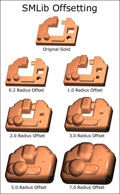
Offset of a Solid
The implementation of the Solid Offsetting Algorithm is relatively simple given the powerful tools available within SMLib. Offsetting utilizes facilities from the SMLib Merge and SMLib Filleting to do most of the difficult work. This unique approach also keeps special case handling to a minimum. The entire algorithm was implemented with two new classes (SmOffsetExecutive and SmOffsetGeometryCreation) and less than 20 new methods of moderate size. The basic approach is as follows:
- Generate faces representing the offsets of existing faces of a solid.
- Insert self-intersection edges of offset faces.
- Generate faces representing the offsets of edges of the solid. This utilizes filleting tools to generate circular blends between corresponding edges of offset faces. In cases where the offset faces have self-intersections, a single edge may require several blends and corner patches.
- Generate offset faces for vertices. We use a triangular trimmed piece of a sphere for simple cases and a complete sphere for some more difficult cases.
- Utilize the “Partial Merge” to put all of the offset faces together. Note that we utilize existing topological relationships eliminate unnecessary surface/surface intersections and speed up the process several orders of magnitude over a straight “Merge”.
- After the “Partial Merge” we need to identify which regions (i.e. volumes) to keep. In most cases this is just the shell bounding the outer region. However, it is possible to create void regions within a solid.
- Call “Make Manifold” with the selected regions to remove all topology elements not bounding the given regions.
This algorithm lends itself to the creation of very large offsets where the offsets of features of the solid intersect each other. This type of offset is ideal for various NC operations. Right now the algorithm works quite well with analytical parts that don’t have freeform fillets, blends, and corner patches. The proper handling of these things requires identification and special handling. The best way to do it is to regenerate the fillets, blends, and corner patches directly from the offset surfaces instead of trying to offset the surface directly. There are also some problems with self-intersecting surfaces that are basically impossible to solve in a reasonable way. For solids with these type of surfaces, it is only possible to create offsets of relatively small radius.
Shelling of a Solid
The implementation of a shelling algorithm required only a few slight modifications to the Offset Solid algorithm:
- We allow the specification of a zero offset distance for a face (currently required to be planar).
- If an edge belongs to the shelling face, we connect the corresponding offsets using a plane instead of a circular blend.
- If a vertex belongs to a shelled face. We blend it using a piece of a plane instead of a sphere.
Once the shelled solid is created it can be used in a number of ways to do very powerful operations.
- Subtraction of original solid or smaller radius offset to create a shelled solid.
- Ribs can be easily created by subtracting thin boxes from inner solid prior to the final difference operation.