Running the cuPHY SDK
The SDK provides the cuPHY library and several examples that link with the library.
Prerequisites
The following instructions assume the system configuration and cuBB SDK installation are done. If not, please see the cuBB Install Guide to complete the installation or upgrade process.
After powering on the system, use the following commands to verify the GPU and NIC are in the correct state:
            # Verify GPU is detected and CUDA driver version matches the release manifest.

$ nvidia-smi
Verify that the NIC is in the correct state on the host (this is only required to run cuBB end-to-end):
            # Verify CX6-DX NIC is detected.

$ sudo lshw -c network -businfo

Bus info          Device     Class          Description
=======================================================
pci@0000:05:00.0  eno1       network        I210 Gigabit Network Connection
pci@0000:06:00.0  enp6s0     network        I210 Gigabit Network Connection
pci@0000:b5:00.0  ens6f0     network        MT2892 Family [ConnectX-6 Dx]
pci@0000:b5:00.1  ens6f1     network        MT2892 Family [ConnectX-6 Dx]

# Verify the link state is right. Assuming NIC port 0 is connected.

$ sudo mlxlink -d b5:00.0

Operational Info
----------------
State                           : Active
Physical state                  : LinkUp
Speed                           : 100G
Width                           : 4x
FEC                             : Standard RS-FEC - RS(528,514)
Loopback Mode                   : No Loopback
Auto Negotiation                : ON

Supported Info
--------------
Enabled Link Speed (Ext.)       : 0x000007f2 (100G_2X,100G_4X,50G_1X,50G_2X,40G,25G,10G,1G)
Supported Cable Speed (Ext.)    : 0x000002f2 (100G_4X,50G_2X,40G,25G,10G,1G)

Troubleshooting Info
--------------------
Status Opcode                   : 0
Group Opcode                    : N/A
Recommendation                  : No issue was observed.
Set up the Host Environment
Set up the environment on both servers. You will need to run aerial-init.sh once each time the
system reboots. Refer to the “System Initialization Script” section in the cuBB Installation Guide
for more details.
$ sudo ./aerial-init.sh
Launch the cuBB Container
Use the following command to launch the cuBB container:
$ sudo docker exec -it cuBB /bin/bash
Build cuPHY SDK in the Container
Build cuPHY in the cuBB container using the following commands:
            $ cd /opt/nvidia/cuBB/cuPHY
$ mkdir build
$ mkdir install
$ cd build
$ cmake .. -DCMAKE_INSTALL_PREFIX=../install -DBUILD_DOCS=ON
$ make -j $(nproc --all)
The BUILD_DOCS=ON option in the example above allows the make to generate the Doxygen
documentation for the cuPHY library API. To disable this option, leave it out from the CMake
command line. The output directory is cuPHY/install/docs.
To put the built cuPHY headers and libraries into an installation directory so that other applications using the cuPHY library can compile and link with cuPHY, use the commands from the current build directory:
$ make install
This creates the include and lib directories under the cuPHY/install directory.
This section describes how to run the cuPHY SDK standalone example programs. They read test vector data files as input. Refer to the supported test vector configurations list in the cuBB Release Notes for what test vectors to use for all the different configurations. Do not use old test vectors from previous cuBB releases with the example programs of this release.
Generating Test Vectors using Matlab 5GModel
Run this Matlab command:
cd('nr_matlab'); startup; [nTC, errCnt] = runRegression({'TestVector'}, {'allChannels'}, 'compact', [0, 1] );
All the cuPHY test vectors are generated and stored under nr_matlab/GPU_test_input.
Instructions for Testing cuPHY Channels Manually
PUSCH
Test Vectors
Match test vector name with PUSCH_gNB_CUPHY.h5
How to Run
Streams mode:
cuPHY/build/examples/pusch_rx_multi_pipe/cuphy_ex_pusch_rx_multi_pipe -i ~/<tv_name>.h5Graphs mode:
cuPHY/build/examples/pusch_rx_multi_pipe/cuphy_ex_pusch_rx_multi_pipe -i ~/<tv_name>.h5 -m 1
Expected Outcome
Test 1 (CRC test KPI): All test cases must have zero CRC errors (only CRC errors, not correct ones, are reported when the channel is run).
PUCCH
Test Vectors
Match test vector name with PUCCH_F*_gNB_CUPHY.h5
How to Run
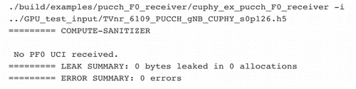
PUCCH format 0/1/2/3: cuPHY/build/examples/pucch_rx_pipeline/cuphy_ex_pucch_rx_pipeline -i <tv_name>
Expected Outcome
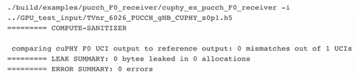
cuphy_ex_pucch_Fx_receiverwill check if the test vector includes PFx UCI first.If the test-vector UCI format is not expected, it will display “No PFx UCI received”.
If the test-vector UCI format is expected, it will compare UCI output.xzsd
PRACH
Test Vectors
Match test vector name with PRACH_gNB_CUPHY.h5
How to Run
cuPHY/build/examples/prach_receiver_multi_cell/prach_receiver_multi_cell -i <tv_name> -r <num_iteration> -k
Expected Outcome
prach_receiver_multi_cellwill compare against the reference measurements in the test vector.Measured values will be displayed and if they are within tolerance the message will be displayed:
========> Test PASS
PDSCH
Test Vectors
Match test vector name with PDSCH_gNB_CUPHY.h5
How to Run
PDSCH in non-AAS mode, streams:
cuPHY/build/examples/pdsch_tx/cuphy_ex_pdsch_tx ~/<tv_name>.h5 2 0 0PDSCH in non-AAS mode, graphs:
cuPHY/build/examples/pdsch_tx/cuphy_ex_pdsch_tx ~/<tv_name>.h5 2 0 1
Expected Outcome
Test 1 (correctness against reference model): Channel reports correct match with reference model
PDCCH
Test Vectors
Match test vector name with PDCCH_gNB_CUPHY.h5
How to Run
Streams mode:
cuPHY/build/examples/pdcch/embed_pdcch_tf_signal -i ~/<tv_name>.h5 -m 0Graphs mode:
cuPHY/build/examples/pdcch/embed_pdcch_tf_signal -i ~/<tv_name>.h5 -m 1
Expected Outcome
Test 1 (correctness against reference model): Test PASS
SSB
Test Vectors
Match test vector name with SSB_gNB_CUPHY.h5
How to Run
Streams mode:
cuPHY/build/examples/ss/testSS -i ~/<tv_name>.h5 -m 0Graphs mode:
cuPHY/build/examples/ss/testSS -i ~/<tv_name>.h5 -m 1
Expected Outcome
Test 1 (correctness against reference model): Test PASS
CSI-RS
Test Vectors
Match test vector name with CSIRS_gNB_CUPHY.h5
How to Run
Streams mode:
cuPHY/build/examples/csi_rs/nzp_csi_rs_test -i <tv_name> -m 0Graphs mode:
cuPHY/build/examples/csi_rs/nzp_csi_rs_test -i <tv_name> -m 1
Expected Outcome
Test 1 (correctness against reference model): Test PASS
Instructions for LDPC Performance Test
The ldpc_perf_collect.py Python script from the cuPHY repository can be used to perform error
rate tests for the cuPHY LDPC decoder. Currently, there are test input files defined for Z = [64, 128, 256, 384],
BG = [1,2]. The current tests check whether the block error rate (BLER, also sometimes referred to
as Frame Error Rate or FER) is less than 0.1.
From the build directory, the following commands will run the tests:
            ../util/ldpc/ldpc_perf_collect.py --mode test -i ../util/ldpc/test/ldpc_decode_BG1_Z64_BLER0.1.txt  -f -w 800 -P
../util/ldpc/ldpc_perf_collect.py --mode test -i ../util/ldpc/test/ldpc_decode_BG1_Z128_BLER0.1.txt -f -w 800 -P
../util/ldpc/ldpc_perf_collect.py --mode test -i ../util/ldpc/test/ldpc_decode_BG1_Z256_BLER0.1.txt -f -w 800 -P
../util/ldpc/ldpc_perf_collect.py --mode test -i ../util/ldpc/test/ldpc_decode_BG1_Z384_BLER0.1.txt -f -w 800 -P
../util/ldpc/ldpc_perf_collect.py --mode test -i ../util/ldpc/test/ldpc_decode_BG2_Z64_BLER0.1.txt  -f -w 800 -P
../util/ldpc/ldpc_perf_collect.py --mode test -i ../util/ldpc/test/ldpc_decode_BG2_Z128_BLER0.1.txt -f -w 800 -P
../util/ldpc/ldpc_perf_collect.py --mode test -i ../util/ldpc/test/ldpc_decode_BG2_Z256_BLER0.1.txt -f -w 800 -P
../util/ldpc/ldpc_perf_collect.py --mode test -i ../util/ldpc/test/ldpc_decode_BG2_Z384_BLER0.1.txt -f -w 800 -P
Each test input file contains multiple tests for different code rates, as specified by the number of parity nodes. The format of the input files has the following form:
Within the util/perf folder, there is a set of Python scripts to automate and simplify performance measurements aimed at characterizing the cell capacity of cuPHY in isolation (i.e., without I/O to and from NIC or layer 2).
The scripts offer the possibility of measuring the following:
Workload latency with peak cells, for the following use cases:
F01 (20MHz cells, 4 layers downlink and 1 layer uplink, numerology index equal to 0) with concurrent reference workloads PDSCH and PUSCH;
F14 (100MHz cells, 16 layers downlink and 8 layers uplink, numerology index equal to 1) with reference concurrent workloads PDSCH and PUSCH.
Capacity with peak + average cells, for the following use cases:
F01 (20MHz cells, 4 layers downlink and 1 layer uplink, numerology index equal to 0) with concurrent reference workloads PDSCH and PUSCH;
F14 (100MHz cells, 16 layers downlink and 8 layers uplink, numerology index equal to 1) with concurrent reference workloads PDSCH and PUSCH.
In all cases, Aerial SDK offers the possibility of measuring the latency of all workloads (PDSCH
and PUSCH) with dynamic and heterogeneous traffic (meaning that each cell is stimulated with a
different test vectors, and every slot will see a different allocation of the test vectors to the
considered cells), and with specific traffic models. Further details on preparing the test vectors
and on using the scripts to conduct the measurements can be found in cuPHY/util/perf/performance.md.