Clara Holoscan Sample Applications
This section explains how to run the Clara Holoscan sample applications. Three sample applications are provided with the SDK:
Tool tracking in endoscopy video using an LSTM model
Hi-speed endoscopy using high resolution and high frame rate cameras
Semantic segmentation bone contours with hyperechoic lines
Each application comes with support for an AJA capture card or replay from a video file included in the sample application container. More information regarding the AI models used for these applications can be found under the Overview section of this document.
To run the sample applications, please follow the instructions in NGC website or Github repository.
Please also ensure that X11 is configured to allow commands from docker:
xhost +local:docker
Digital endoscopy is a key technology for medical screenings and minimally invasive surgeries. Using real-time AI workflows to process and analyze the video signal produced by the endoscopic camera, this technology helps medical professionals with anomaly detection and measurements, image enhancements, alerts, and analytics.
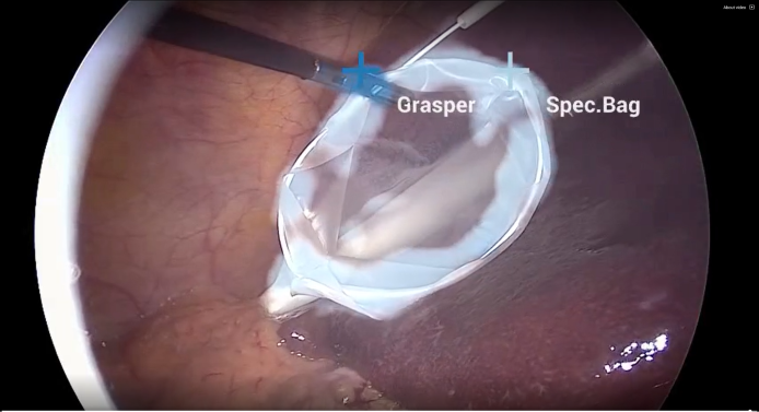
Fig. 6 Endoscopy image from a gallbladder surgery showing AI-powered frame-by-frame tool identification and tracking. Image courtesy of Research Group Camma, IHU Strasbourg and the University of Strasbourg
The Endoscopy tool tracking application provides an example of how an endoscopy data stream can be captured and processed using the GXF framework and C++ API on multiple hardware platforms.
Input source: Video Stream Replayer
The GXF pipeline in a graph form is defined at apps/endoscopy_tool_tracking_gxf/tracking_replayer.yaml in Holoscan Embedded SDK Github Repository.
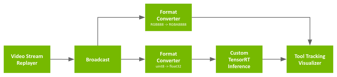
Fig. 7 Tool tracking application workflow with replay from file
The pipeline uses a recorded endoscopy video file (generated by convert_video_to_gxf_entities script) for input frames.
Each input frame in the file is loaded by Video Stream Replayer and Broadcast node passes the frame to the following two nodes (Entities):
Format Converter: Convert image format from
RGB888(24-bit pixel) toRGBA8888(32-bit pixel) for visualization (Tool Tracking Visualizer)Format Converter: Convert the data type of the image from
uint8tofloat32for feeding into the tool tracking model (by Custom TensorRT Inference)
Then, Tool Tracking Visualizer uses outputs from the first Format Converter and Custom TensorRT Inference to render overlay frames (mask/point/text) on top of the original video frames.
To run the Endoscopy Tool Tracking Application with the recorded video as source, run the following commands after setting up the Holoscan SDK:
In the runtime container (from NGC):
            cd /opt/holoscan_sdk

# Endoscopy tool tracking (GXF) from recorded video
./apps/endoscopy_tool_tracking_gxf/tracking_replayer

# Endoscopy tool tracking (C++ API) from recorded video
# 1. Make sure that 'source' is set to 'replayer' in app_config.yaml
sed -i -e 's#^source:.*#source: replayer#' ./apps/endoscopy_tool_tracking/app_config.yaml
# 2. Run the application
./apps/endoscopy_tool_tracking/endoscopy_tool_tracking
In the development container (from source):
            cd /workspace/holoscan-sdk/build

# Endoscopy tool tracking (GXF) from recorded video
./apps/endoscopy_tool_tracking_gxf/tracking_replayer

# Endoscopy tool tracking (C++ API) from recorded video
# 1. Make sure that 'source' is set to 'replayer' in app_config.yaml
sed -i -e 's#^source:.*#source: replayer#' ./apps/endoscopy_tool_tracking/app_config.yaml
# 2. Run the application
LD_LIBRARY_PATH=$(pwd):$(pwd)/lib:$LD_LIBRARY_PATH ./apps/endoscopy_tool_tracking/endoscopy_tool_tracking
Input source: AJA
The GXF pipeline in a graph form is defined at apps/endoscopy_tool_tracking_gxf/tracking_aja.yaml in Holoscan Embedded SDK Github Repository.
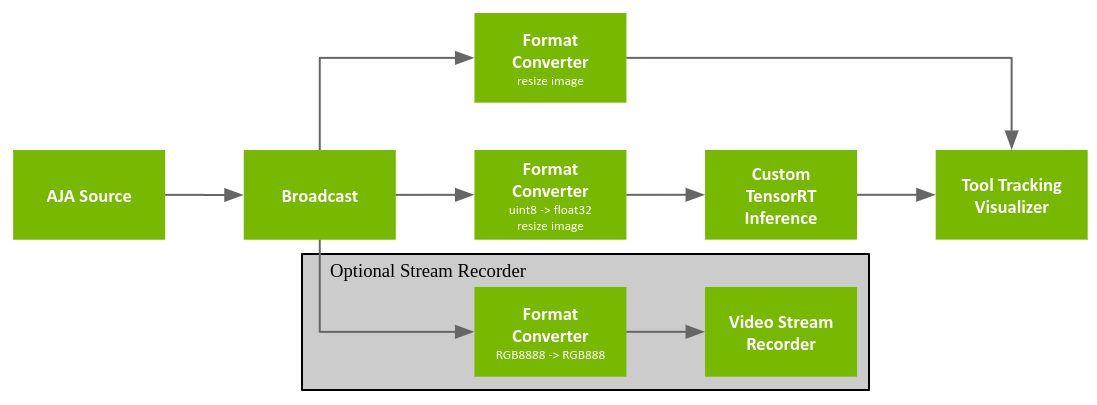
Fig. 8 AJA tool tracking app
The pipeline is similar with Input source: Video Stream Replayer but the input source is replaced with AJA Source.
The pipeline graph also defines an optional Video Stream Recorder that can be enabled to record the original video stream to disk. This stream recorder (and its associated Format Converter) are commented out in the graph definition and thus are disabled by default in order to maximize performance. To enable the stream recorder, uncomment all of the associated components in the graph definition.
AJA Source: Get video frame from AJA HDMI capture card (pixel format is
RGBA8888with the resolution of 1920x1080)Format Converter: Convert image format from
RGB8888(32-bit pixel) toRGBA888(24-bit pixel) for recording (Video Stream Recorder)Video Stream Recorder: Record input frames into a file
Please follow these steps to run the Endoscopy Tool Tracking Application:
To run the Endoscopy Tool Tracking Application with AJA capture, run the following commands after setting up the Holoscan SDK and your AJA system:
In the runtine container (from NGC):
            cd /opt/holoscan_sdk/

# Endoscopy tool tracking (GXF) with AJA
./apps/endoscopy_tool_tracking_gxf/tracking_aja

# Endoscopy tool tracking (C++ API) with AJA
# 1. Make sure that 'source' is set to 'aja' in app_config.yaml
# (To enable recording, you can also update the value for 'do_record' to 'true'.)
sed -i -e 's#^source:.*#source: aja#' ./apps/endoscopy_tool_tracking/app_config.yaml
# 2. Run the application
./apps/endoscopy_tool_tracking/endoscopy_tool_tracking
In the development container (from source):
            cd /workspace/holoscan-sdk/build

# Endoscopy tool tracking (GXF) with AJA
./apps/endoscopy_tool_tracking_gxf/tracking_aja

# Endoscopy tool tracking (C++ API) with AJA
# 1. Make sure that 'source' is set to 'aja' in app_config.yaml
# (To enable recording, you can also update the value for 'do_record' to 'true'.)
sed -i -e 's#^source:.*#source: aja#' ./apps/endoscopy_tool_tracking/app_config.yaml
# 2. Run the application
LD_LIBRARY_PATH=$(pwd):$(pwd)/lib:$LD_LIBRARY_PATH ./apps/endoscopy_tool_tracking/endoscopy_tool_tracking
The hi-speed endoscopy application showcases how high resolution cameras can be used to capture the scene, processed on GPU and displayed at high frame rate using the GXF framework. This application requires Emergent Vision Technologies camera and a display with high refresh rate to keep up with camera’s framerate. This sections also explains how to enable GSYNC for the display, if GSYNC enabled monitor is available, how to install and enable GPUDirect RDMA, and how to enable exclusive display mode for better performance.
Note that this application is meant to be run directly on the device without using docker.
The GXF pipeline in a graph form is defined at apps/hi_speed_endoscopy_gxf/hi_speed_endoscopy.yaml in Holoscan Embedded SDK Github Repository.

Fig. 9 Hi-Speed Endoscopy App
The data acquisition happens using emergent-source, by default it is set to 4200x2160 at 240Hz. The acquired data is then demosaiced in GPU using CUDA via
bayer-demosaic and displayed through holoviz-viewer.
Follow below steps to run the Hi-Speed Endoscopy Application:
To run the Hi-Speed Endoscopy Application, follow below commands after setting up the Holoscan SDK to run from source and your EVT camera.
On the local environment (from source):
Configure and build the project with
HOLOSCAN_BUILD_HI_SPEED_ENDO_APPoption asON.
            cd ${PATH_TO_SDK_REPOSITORY}
cmake -S . -B build \
  -D CMAKE_BUILD_TYPE=Release \
  -D CUDAToolkit_ROOT:PATH=/usr/local/cuda \
  -D CMAKE_CUDA_COMPILER:PATH=/usr/local/cuda/bin/nvcc \
  -D HOLOSCAN_BUILD_HI_SPEED_ENDO_APP=ON
cmake --build build -j
Run the application
            cd ${PATH_TO_SDK_REPOSITORY}/build
sudo ./apps/hi_speed_endoscopy_gxf/hi_speed_endoscopy
Currently this application has hardcoded the camera controls within the
emergent-source. Once the user updated the gxf-extension, the project would need
to be rebuild as mentioned in step 1. above. For more information on the controls,
refer to EVT Camera Attributes Manual.
Enable G-SYNC for Display
To get better performance, the application can be run with a G-SYNC enabled display. To enable G-SYNC for the display, a G-SYNC enabled display is required. This app has been tested with two G-SYNC enabled displays: Asus ROG Swift PG279QM and Asus ROG Swift 360 Hz PG259QNR.
Follow below steps to enable G-SYNC for the display using nvidia-settings.
Open
nvidia-settingsusing terminal. This step requires a graphical user interface.
nvidia-settings
This will open the NVIDIA Settings window.
Click on
X Server Display Configurationand thenAdvancedbutton. This will show optionAllow G-SYNC on monitor not validated as G-SYNC compatible, select the option and clickApply. The window would look like below.
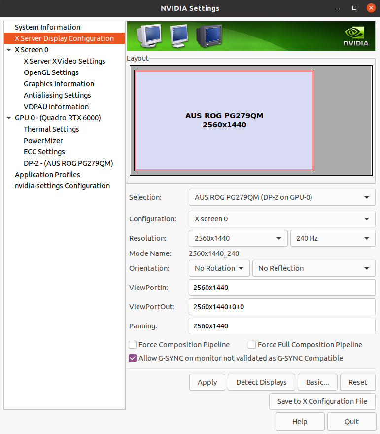
Fig. 10 Enable G-SYNC for the current display
To show the refresh rate and G-SYNC label on the display window, click on
OpenGL Settingsfor the selected display. Now clickAllow G-SYNC/G-SYNC CompatibleandEnable G-SYNC/G-SYNC Compatible Visual Indicatoroptions and clickQuit. This step is shown in below image. TheGsyncindicator will be at the top right screen once the application is running.
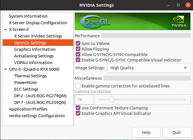
Fig. 11 Enable Visual Indicator for the current display
Installing and Enabling GPUDirect RDMA
The GPUDirect drivers must be installed to enable the use of GPUDirect when using an RTX6000 or RTX A6000 add-in dGPU.
The GPUDirect drivers are not installed by SDK Manager, even when Rivermax SDK is installed, so these steps must always be followed to enable GPUDirect support when using the dGPU.
Download GPUDirect Drivers for OFED:
nvidia-peer-memory_1.1.tar.gz If the above link does not work, navigate to the Downloads section on the GPUDirect page.
Install GPUDirect:
            mv nvidia-peer-memory_1.1.tar.gz nvidia-peer-memory_1.1.orig.tar.gz
tar -xvf nvidia-peer-memory_1.1.orig.tar.gz
cd nvidia-peer-memory-1.1
dpkg-buildpackage -us -uc
sudo dpkg -i ../nvidia-peer-memory_1.1-0_all.deb
sudo dpkg -i ../nvidia-peer-memory-dkms_1.1-0_all.deb
sudo service nv_peer_mem start
Verify the nv_peer_mem service is running:
sudo service nv_peer_mem status
Enable the nv_peer_mem service at boot time:
            sudo systemctl enable nv_peer_mem
sudo /lib/systemd/systemd-sysv-install enable nv_peer_mem
To enable the GPUDirect RDMA on NVIDIA IGX Orin Developer Kit, update your firmware with instructions from the NVIDIA IGX Orin Developer Kit User Guide or the below command needs to be executed at every single bootup.
sudo setpci -s 0007:02:00.0 ecap_acs+6.w=0
Update the hi-speed-endoscopy application to set
use_rdmaastrue.
            vi ${PATH_TO_SDK_REPOSITORY}/apps/hi_speed_endoscopy_gxf/hi_speed_endoscopy.yaml
# Set `use_rdma` as `true`
Save the file and build the application again. To build the source locally please refer to README.md.
To run application, use below run command:
            cd ${PATH_TO_SDK_REPOSITORY}/build
sudo MELLANOX_RINGBUFF_FACTOR=14 ./apps/hi_speed_endoscopy_gxf/hi_speed_endoscopy
The MELLANOX_RINGBUFF_FACTOR is used by EVT driver to decide how much BAR1 size
memory would be used on the dGPU. It can be changed to different number based for
different use cases.
Enabling Exclusive Display Mode
By default, the application uses a borderless fullscreen window which is managed by the window manager. Because the window manager also manages other applications, the hi-speed-endoscopy application may suffer a performance hit. To improve performance, exclusive display mode can be used which allows the application to bypass the window manager and render directly to the display.
To enable exclusive display follow below steps.
Find the name of the display connected using
xrandr. As an example the output of thexrandrcould look like below.
            $ xrandr
Screen 0: minimum 8 x 8, current 4480 x 1440, maximum 32767 x 32767
DP-0 disconnected (normal left inverted right x axis y axis)
DP-1 disconnected (normal left inverted right x axis y axis)
DP-2 connected primary 2560x1440+1920+0 (normal left inverted right x axis y axis) 600mm x 340mm
   2560x1440     59.98 + 239.97*  199.99   144.00   120.00    99.95
   1024x768      60.00
   800x600       60.32
   640x480       59.94
DP-3 disconnected (normal left inverted right x axis y axis)
DP-4 disconnected (normal left inverted right x axis y axis)
DP-5 disconnected (normal left inverted right x axis y axis)
DP-6 disconnected (normal left inverted right x axis y axis)
DP-7 connected 1920x1080+0+0 (normal left inverted right x axis y axis) 543mm x 302mm
   1920x1080     60.00*+ 119.88    59.94    50.00    23.98
   1280x720      59.94    50.00
   1024x768      60.00
   800x600       60.32
   720x576       50.00
   720x480       59.94
   640x480       59.94    59.93
USB-C-0 disconnected (normal left inverted right x axis y axis)
In this example DP-2 is the name of the display connected to the Clara devkit that
will be used for exclusive display.
The name of the display can also be found in tab X Server Display Configuration
in nvidia-settings. See figure Enable G-SYNC for the current display.
Update the hi-speed-endoscopy application to use the display name, resolution and framerate used by the connected display. In addition to that, add
use_exclusive_displayastrueotherwise the exclusive display will not be enabled in the app.
            vi ${PATH_TO_SDK_REPOSITORY}/apps/hi_speed_endoscopy_gxf/hi_speed_endoscopy.yaml
# Add below lines as parameters for entity holoviz and component nvidia::holoscan::HolovizViewer
# display_name: DP-2
# width: 2560
# height: 1440
# framerate: 240
# use_exclusive_display: true
Save the file and build the application again. To build the source locally please refer to README.md.
If a single display is connected, ssh to Clara devkit and stop the X server.
            ssh ${DEVKIT_USER}@${IP_ADDRESS}
export DISPLAY=:1
xhost +
sudo systemctl stop display-manager
Set
${DEVKIT_USER}and${IP_ADDRESS}to your Clara devkit credentials.Display
:1is just an example, it could be:0or different.To start the
display manager, after done running the application, use command:
sudo systemctl start display-manager
If multiple displays are connected, the display to be used in exclusive
mode needs to be disabled in the nvidia-settings. Open the
X Server Display Configuration tab, select the display and under Confguration
select Disabled. Press Apply.
To enable the display after done running the application, start nvidia-settings.
Open the X Server Display Configuration tab, select the display and under
Confguration select X screen 0. Press Apply.
Now, run the application.
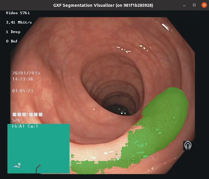
This section describes the details of the ultrasound segmentation sample application as well as how to load a custom inference model into the application for some limited customization. Out of the box, the ultrasound segmentation application comes as a “video replayer” and “AJA source”, where the user can replay a pre-recorded ultrasound video file included in the runtime container or stream data from an AJA capture device directly through the GPU respectively.
This application performs an automatic segmentation of the spine from a trained AI model for the purpose of scoliosis visualization and measurement.
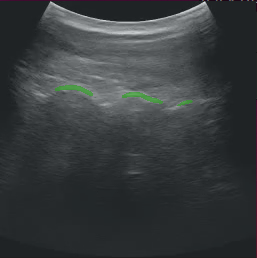
Fig. 12 Spine segmentation of ultrasound data
Input source: Video Stream Replayer
The replayer pipeline is defined in apps/ultrasound_segmentation/segmentation_replayer.yaml in Holoscan Embedded SDK Github Repository.
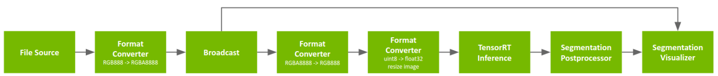
Fig. 13 Segmentation application with replay from file
The pipeline uses a pre-recorded endoscopy video stream stored in nvidia::gxf::Tensor format as input. The tensor-formatted file is generated via convert_video_to_gxf_entities from a pre-recorded MP4 video file.
Input frames are loaded by Video Stream Replayer and Broadcast node passes the frame to two branches in the pipeline.
In the inference branch the video frames are converted to floating-point precision using the format converter, pixel-wise segmentation is performed, and the segmentation result if post-processed for the visualizer.
The visualizer receives the original frame as well as the result of the inference branch to show an overlay.
To run the Ultrasound Segmentation Application with the recorded video as source, run the following commands after setting up the Holoscan SDK:
In the runtime container (from NGC):
            cd /opt/holoscan_sdk
./apps/ultrasound_segmentation_gxf/segmentation_replayer
In the development container (from source):
            cd /workspace/holoscan-sdk/build
./apps/ultrasound_segmentation_gxf/segmentation_replayer
Input source: AJA
The AJA pipeline is defined in apps/ultrasound_segmentation/segmentation_aja.yaml in Holoscan Embedded SDK Github Repository.
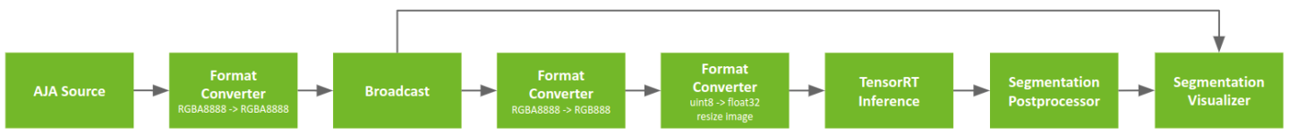
Fig. 14 AJA segmentation app
This pipeline is exactly the same as the pipeline described in the previous section except the Video Stream Replayer has been substituted with an AJA Video Source.
To run the Ultrasound Segmentation Application with AJA capture, run the following commands after setting up the Holoscan SDK and your AJA system:
In the runtime container (from NGC):
            cd /opt/holoscan_sdk
./apps/ultrasound_segmentation_gxf/segmentation_aja
In the development container (from source):
            cd /workspace/holoscan-sdk/build
./apps/ultrasound_segmentation_gxf/segmentation_aja
Bring Your Own Model (BYOM) - Customizing the Ultrasound Segmentation Application For Your Model
This section shows how the user can easily modify the ultrasound segmentation app to run a different segmentation model, even of an entirely different modality. In this use case we will use the ultrasound application to implement a polyp segmentation model to run on a Colonoscopy sample video.
At this time the runtime containers contain only binaries of the sample applications, meaning users may not modify the extensions. However, the users can substitute the ultrasound model with their own and add, remove, or replace the extensions used in the application.
As a first step, please go to the Colonoscopy Sample Application Data NGC Resource to download the model and video data.
For a comprehensive guide on building your own Holoscan extensions and apps please refer to Clara Holoscan Development Guide.
The sample ultrasound segmentation model expects a gray-scale image of 256 x 256 and outputs a semantic segmentation of the same size with two channels representing bone contours with hyperechoic lines (foreground) and hyperechoic acoustic shadow (background).
Currently, the sample apps are able to load ONNX models, or TensorRT engine files built for the architecture on which you will be running the model only. TRT engines are automatically generated from ONNX by the application when it is run.
If you are converting your model from PyTorch to ONNX, chances are your input is NCHW, and will need to be converted to NHWC. An example transformation script is included with the colonoscopy sample downloaded above, and is found inside the resource as model/graph_surgeon.py. You may need to modify the dimensions as needed before modifying your model as:
python graph_surgeon.py {YOUR_MODEL_NAME}.onnx {DESIRED_OUTPUT_NAME}.onnx
Note that this step is optional if you are directly using ONNX models.
To get a better understanding of the model, appplications such as netron.app can be used.
We will now substitute the model and sample video to inference upon as follows.
Enter the sample application container, but make sure to load the colonoscopy model from the host into the container. Assuming your model is in
${my_model_path_dir}and your data is in${my_data_path_dir}then you can execute the following:docker run -it --rm --runtime=nvidia \ -e NVIDIA_DRIVER_CAPABILITIES=graphics,video,compute,utility \ -v ${my_model_path_dir}:/workspace/my_model \ -v ${my_data_path_dir}:/workspace/my_data \ -v /tmp/.X11-unix:/tmp/.X11-unix \ -e DISPLAY=${DISPLAY} \ nvcr.io/nvidia/clara-holoscan/clara_holoscan_sample_runtime:v0.3.0-arm64
Check that the model and data correctly appear under
/workspace/my_modeland/workspace/my_data.Now we are ready to make the required modifications to the ultrasound sample application to have the colonoscopy model load.
            cd /opt/holoscan_sdk
vi ./apps/ultrasound_segmentation_gxf/segmentation_replayer.yaml
In the editor navigate to the first entity
source, and under typenvidia::holoscan::stream_playback::VideoStreamReplayerwe will modify the following for our input video:a.
directory: "/workspace/my_data"b.
basename: "colonoscopy"TipIn general, to be able to play a desired video through a custom model we first need to convert the video file into a GXF replayable tensor format. This step has already been done for the colonoscopy example, but for a custom video perform the following actions inside the container.
            apt update && DEBIAN_FRONTEND=noninteractive apt install -y ffmpeg
cd /workspace
git clone https://github.com/NVIDIA/clara-holoscan-embedded-sdk.git
cd clara-holoscan-embedded-sdk/scripts
ffmpeg -i /workspace/my_data/${my_video} -pix_fmt rgb24 -f rawvideo pipe:1 | python3 convert_video_to_gxf_entities.py --width ${my_width} --height ${my_height} --directory /workspace/my_data --basename my_video
The above commands should yield two Holoscan tensor replayer files in
/workspace/my_data, namelymy_video.gxf_indexandmy_video.gxf_entities.In the editor navigate to the
segmentation_preprocessorentity. Under typenvidia::holoscan::formatconverter::FormatConverterwe will modify the following parameters to fit the input dimensions of our colonoscopy model:a.
resize_width: 512b.
resize_height: 512In the editor navigate to the
segmentation_inferenceentity. We will modify thenvidia::gxf::TensorRtInferencetype where we want to specify the input and output names.a. Specify the location of your
ONNXfiles as:model_file_path: /workspace/my_model/colon.onnxb. Specify the location of TensorRT engines as:
engine_cache_dir: /workspace/my_model/cachec. Specify the names of the inputs specified in your model under
input_binding_names. In the case of ONNX models converted from PyTorch inputs names take the formINPUT__0.d. Specify the names of the inputs specified in your model under
output_binding_names. In the case of ONNX models converted from PyTorch and then thegraph_surgeon.pyconversion, names take the formoutput_old.Assuming the custom model input and output bindings are
MY_MODEL_INPUT_NAMEandMY_MODEL_OUTPUT_NAME, thenvidia::gxf::TensorRtInferencecomponent would result in:- type: nvidia::gxf::TensorRtInference parameters: input_binding_names: - MY_MODEL_INPUT_NAME output_binding_names: - MY_MODEL_OUTPUT_NAME
TipThe
nvidia::gxf::TensorRtInferencecomponent binds the names of the Holoscan component inputs to the model inputs via theinput_tensor_namesandinput_binding_nameslists, where the first specifies the name of the tensor used by the Holoscan componentnvidia::gxf::TensorRtInferenceand the latter specifies the name of the model input. Similarly,output_tensor_namesandoutput_binding_nameslink the component output names to the model output (see extensions).In the entity
segmentation_postprocessor, make the following change:network_output_type: sigmoid.In the entity
segmentation_visualizer, we will make the following changes undernvidia::holoscan::segmentation_visualizer::Visualizerto correctly input the dimensions of our video and the output dimensions of our model:a.
image_width: 720b.
image_height: 576c.
class_index_width: 512d.
class_index_height: 512Run the application with the new model and data.
            cd /opt/holoscan_sdk
./apps/ultrasound_segmentation_gxf/segmentation_replayer