

DPS UI Operator Guide#
Use the DPS UI to inspect configuration and operational state, create inactive topology candidates, manage policy bundles, and prepare resource groups for activation. Dynamic Power Software remains authoritative for supported configuration, installed policy definitions, and the outcome of every write.
The examples and images in this guide use a fixed set of locally generated
test data. Names such as
east-hall, guide-topology, and e2e-operator are synthetic. They are not
customer or production data.
Before You Begin#
Sign in with the authentication method configured for your deployment. Do not include credentials, secrets, OAuth callback values, browser-session data, or access tokens in screenshots, logs, diagnostic files, or other materials you share for troubleshooting.
The UI applies DPS role-based access control (RBAC). Read access lets you inspect inventory, status, and current configuration. Write access exposes creation, update, validation, and activation controls. A missing or disabled control usually means your role, the deployment capability, or the current DPS state does not permit the action. Resolve the displayed error or request the required access.
Use the safety conventions in this table throughout the guide.
Label |
Meaning |
Operator Action |
|---|---|---|
Read-only |
Retrieves or displays DPS data. |
Verify the selected topology, resource group, or task. |
Write |
Changes a stored object or configuration. |
Review the object, scope, and confirmation text. |
Guarded operation |
Can affect lifecycle state, capacity, or another operator’s configuration. |
Confirm the operational plan and recovery path before acknowledging the action. |
Warning
Validation checks the request that DPS receives at that time. A later edit invalidates the result. Successful validation does not make an import or activation safe by itself.
The workflows in this guide are independent. Use On this page to navigate directly to the workflow you need.
Orient Yourself in the UI#
After you sign in, use Dashboard as the operator starting point. The left navigation groups infrastructure, power control, operations, and administration views. Use the dashboard to identify the active topology, data-quality signals, and links to detailed views. Dashboard values are the latest reported UI view; they do not replace a successful configuration, activation, or task result.
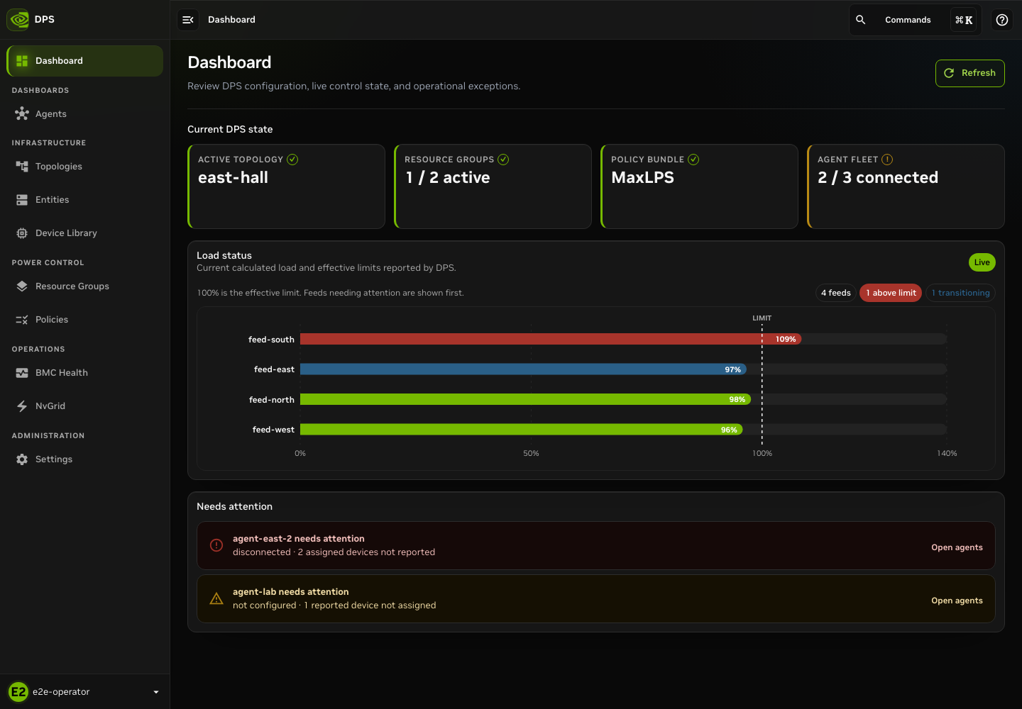
Dashboard and primary navigation using synthetic data.
Every authenticated page that includes contextual guidance provides Help for this page in the top bar. The drawer describes the page, supplies safe-use notes, and can open a read-only in-product tutorial. It highlights controls but does not perform actions for you.
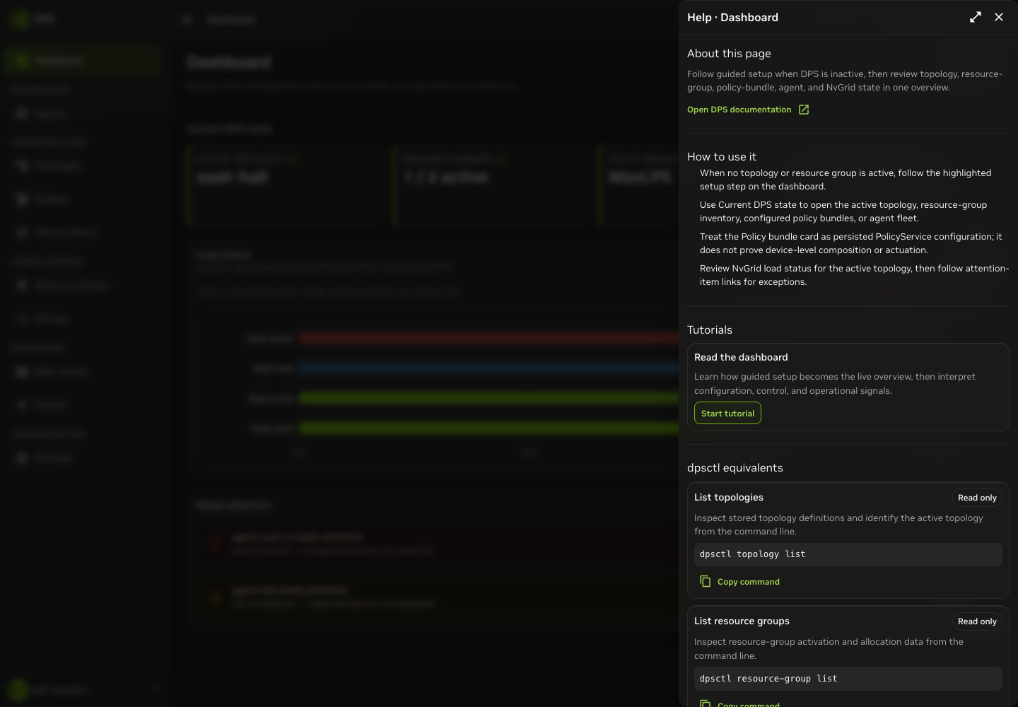
Page Help changes with the route. Open it before you use an unfamiliar page.
Create, Validate, and Inspect a Topology#
A topology models the hierarchy of power domains and compute resources. Build and inspect a candidate while it is inactive. Treat activation as a separate, reviewed change.
Start from the Catalog#
Open Topologies and identify the active topology before you take action. Search and filter the catalog. The active topology is the one currently used in production. Inactive rows are suitable candidates for inspection, editing, and a later activation decision.
Select Create to start a local draft. Select Clone when a saved topology is the correct starting point. Cloning changes a local copy, not the source topology. Use Import for a canonical JSON manifest that already exists outside the builder.
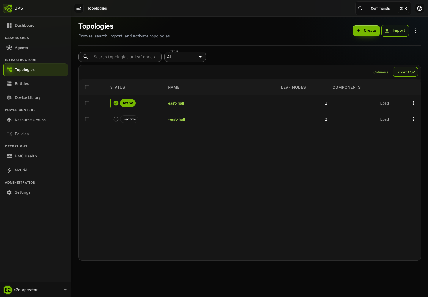
Identify the active topology before you select a candidate row.
Create a Power Domain#
The Topology Builder is a local workspace. It does not write to DPS until you import the later manifest. The draft remains in the browser, which makes it suitable for review, but it is not a shared server-side record.
To create a power domain at the root of an NVL72 rack topology, complete these steps.
Select Add entity.
Select PowerDomain as the root type and enter a unique Entity name. This example uses
power-domain-a.Select a registered model if the entity type requires one, and then select Save entity.
Enter a clear, unique Topology name. Add Topology properties only as a valid JSON object.
Review the summary chips and Readiness panel. They report entity, root, compute, leaf, and depth counts, and identify issues that block validation.
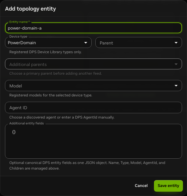
Create power-domain-a as the PowerDomain root for the NVL72 example.
Add a Rack#
Select + Child on power-domain-a in the single-line diagram. The entity
editor opens with power-domain-a selected as Parent. Set Device type
to PowerDistribution, select the registered PDU Model, name the child
nvl72-rack-a, confirm its parent, and select Save entity.
The rack is a PowerDistribution device, not a nested PowerDomain. Use the
registered Device Library model that represents the rack power-distribution
unit. Keep the same parent relationship: power-domain-a > nvl72-rack-a.
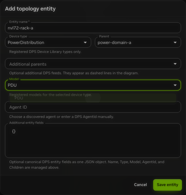
The nvl72-rack-a PowerDistribution device uses the PDU model and is
parented to power-domain-a before you add compute systems.
Add Multiple Entities at Once#
Use Add multiple to create uniform systems in a rack without opening a separate editor for each system.
Create and save the rack parent. This example uses
nvl72-rack-a.Select Add multiple from the builder actions or Entity hierarchy.
Set Device type to ComputerSystem.
Select the registered Model for every system. This example uses
DGX_GB200.Enter
18for Number of entities.Set Parent to
nvl72-rack-a. Confirm that the helper text identifies the parent for every new entity.Select Add entities. The builder creates
computer-system-1throughcomputer-system-18. Use Edit if your naming convention requires more specific names.Confirm the compute count, Entity hierarchy parent column, and lines in the single-line diagram before you review the manifest.
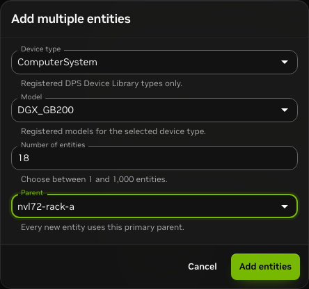
Multi-add configuration for 18 ComputerSystem entities with
nvl72-rack-a as the primary parent.
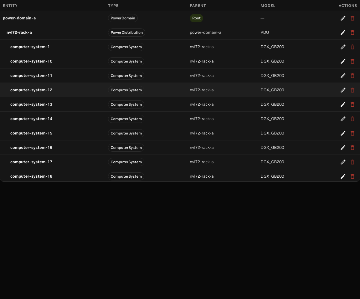
The entity hierarchy confirms the PowerDistribution rack and generated
ComputerSystem children. computer-system-18 confirms the full multi-add
range.
The single-line diagram and Entity hierarchy table show the same local draft. A solid line indicates the primary layout parent. A dashed line indicates an additional feed. Use Edit to review type, model, parent, and additional parents. Fit topology in view changes only the camera. It does not change the topology model.
Resolve every Readiness item before you continue. Common blockers include an empty or duplicate name, an invalid parent relationship, a missing Device Library model, a cycle, and invalid topology-properties JSON. A clean diagram does not validate a topology. Review and validate becomes available only when the local draft is ready and the Device Library is available.
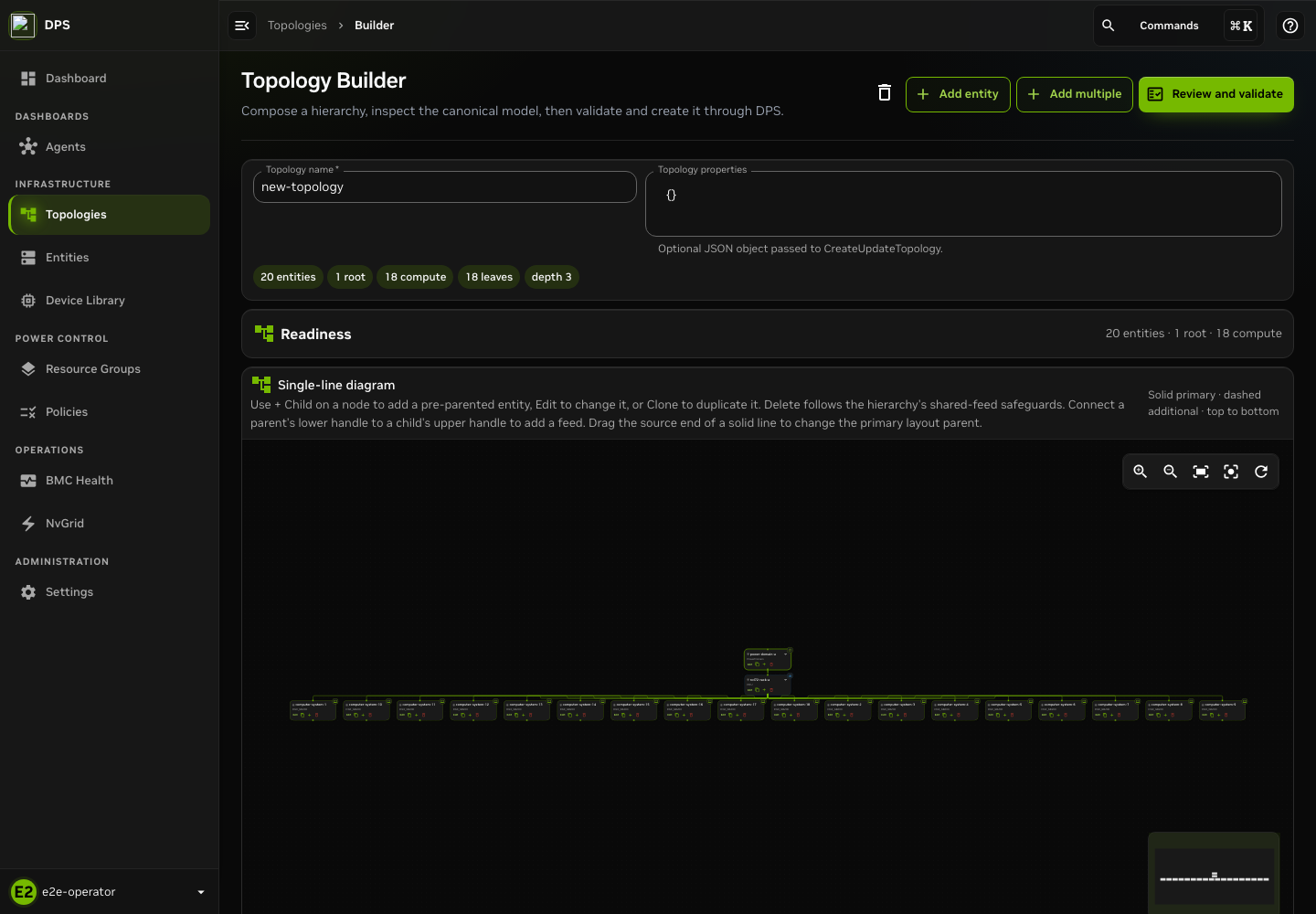
Complete local NVL72 example with 20 entities, one root, and 18 compute systems.
Review the Topology#
Select Review and validate. The builder converts the local draft to a canonical manifest and opens Import Topology. DPS has not changed at this point. Review these items before you send anything to the server.
Confirm that Topology name is the intended name.
Confirm that Import preview reports the expected counts for data center entities, topology entities, roots, and connections. The policy count must be zero.
Confirm that Topology manifest contains every entity with the intended type, model, parent and child relationships, and properties.
If you change the name or JSON, validate the changed manifest again.
Select Validate topology and wait for the manifest to show Validated. Validation checks the complete payload at the server. Builder readiness does not replace server validation.
Import Your Built Topology#
After validation succeeds, review the Operator actions card. A manifest
that creates or updates data center entities can complete those writes before
a later topology stage fails. The UI acknowledgment can mention policies for
compatibility, but current imports must keep the legacy Policies array empty;
a nonempty array is rejected. Select the acknowledgment only after reviewing
the exact manifest, and then select Import topology.
If DPS returns an error, retain the manifest and error details for correction. Do not assume that a failed import fully rolled back. If the import succeeds, it creates an Inactive topology. Return to the catalog and confirm the topology name and Inactive status before you plan activation.
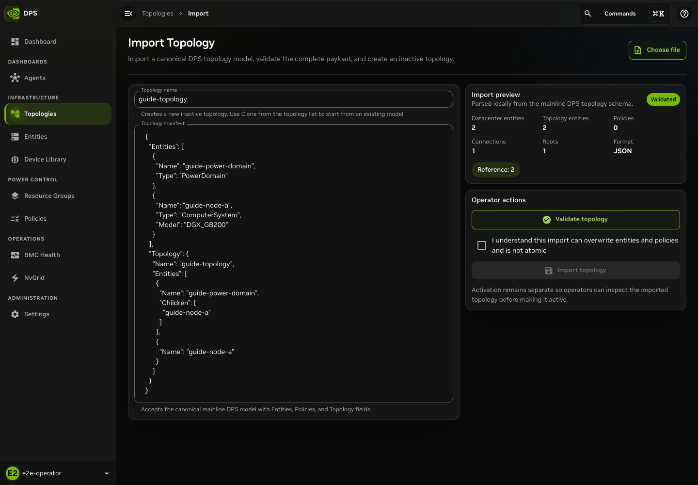
A validated manifest with the non-atomic write acknowledgment selected. Import remains a separate write.
Inspect a Topology#
The import example creates guide-topology. Select that topology, or the one
you imported, to inspect it. The following screenshot uses the separate
east-hall example. In Topology Explorer, use the entity tree,
search, graph layout selector, and Fit topology in view to make the
hierarchy readable. Select a resource to inspect its details. Compare the
explorer with Members and Model before you make an activation decision.
Resource-group, current-power, and node-power-cap overlays report operational
information. Treat them as reported state, not as confirmation that a
configuration was applied.
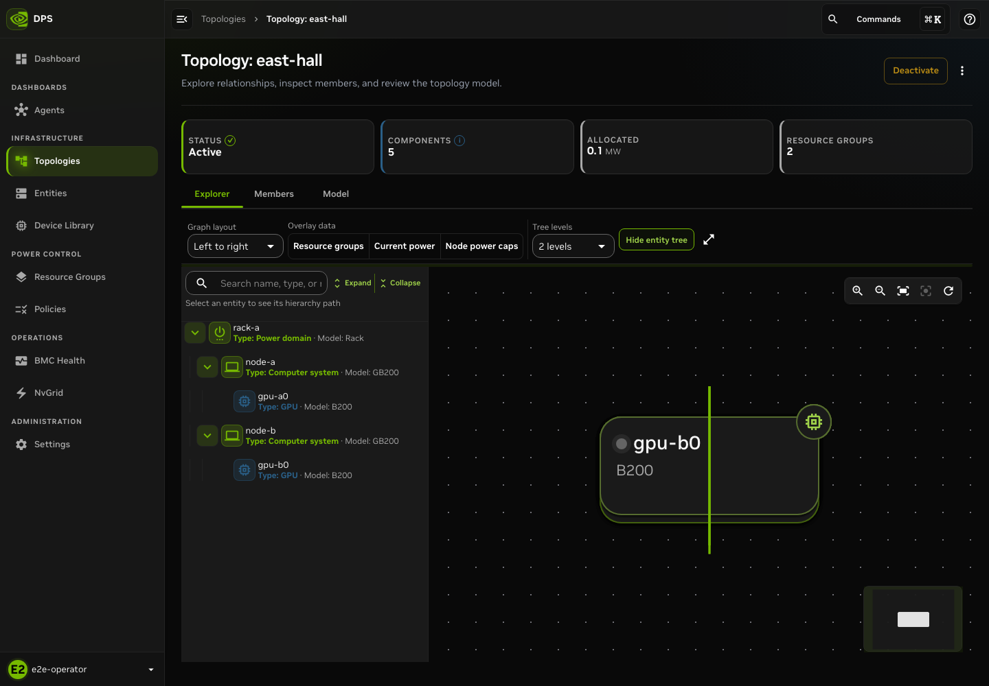
Topology Explorer for the east-hall topology.
Activate a Topology#
Import creates or updates an inactive topology. Activation is a later catalog action that makes that topology active and can deactivate the currently active topology. In the catalog, open the inactive row actions and select Activate. The confirmation identifies the candidate and states whether it deactivates a current topology.
For the first activation, decide whether DPS should Ping hosts before activation. Set a valid Minimum successful (%) threshold. If the dialog lists Active resource groups, review them with the owning operator because DPS can reevaluate them after the switchover. Select Activate only when the confirmation, topology impact, resource-group impact, and change-control approval match the intended work.
After the server responds, return to the catalog and Explorer. Record the reported active state and any per-node activation result. A graph alone does not prove that policies or reachability checks completed.
Manage Policy Bundles and Set the Global Default#
Policy bundles are complete policy sets stored by DPS. The Policies > Bundles page separates two areas:
DPS default bundles are the pinned defaults eligible for the durable global default: MaxP, MaxQ, and MaxLPS.
Other bundles are custom bundles from the current server page.
DPS supplies the embedded policy definitions, scopes, and write result. Do not infer a bundle effect from its name.
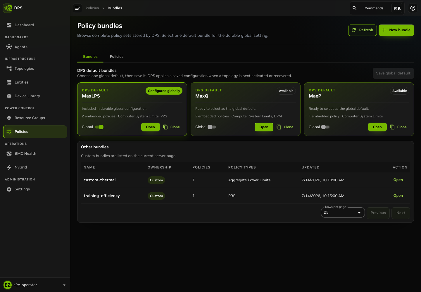
This example uses MaxLPS as the current global setting. MaxQ and MaxP are available alternatives. Custom bundles appear separately.
Inspect, Clone, Create, and Edit Bundles#
Use this procedure to work with policy bundles.
Open a default or custom bundle and inspect the embedded policies and scopes.
Select Clone to use a DPS default as a starting point, and save the clone under a new custom name.
Select New bundle to compose a custom bundle. Select Edit to modify a custom bundle. Both actions require
policy:write.Review the complete bundle before you save it. Saving is a server write. It does not select the bundle or apply it anywhere.
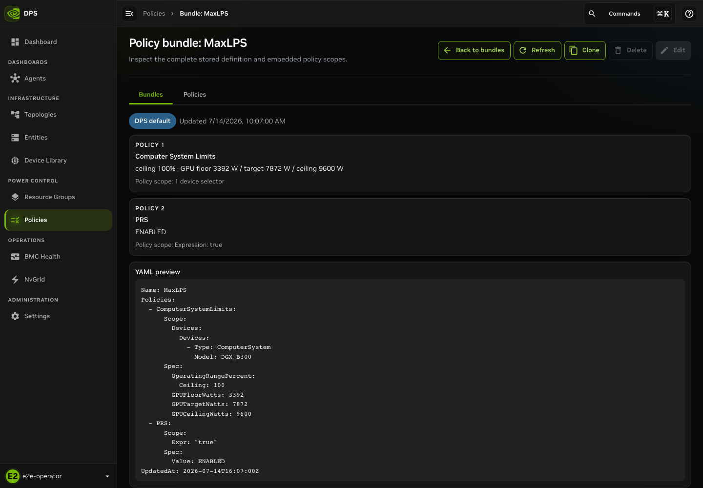
Bundle detail displays the stored definition from DPS.
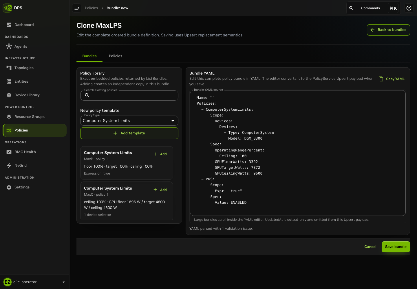
Cloning creates an editable custom-bundle draft. Supply a unique name before you save it.
Set the Global Default Policy Bundle#
The UI stores the selected default in the durable
global_policy_bundle configuration setting. This setting is not a command to
immediately apply a per-device or per-topology policy.
Out of the box, MaxLPS is the configured global default. It remains selected unless an operator saves MaxP or MaxQ as its replacement, or intentionally removes the global default.
Open Policies > Bundles and locate DPS default bundles.
Review each card state. Configured globally is the setting read from DPS. Current setting remains effective while another choice is staged. Pending save identifies the staged replacement.
Turn on Global for exactly one of MaxP, MaxQ, or MaxLPS. Selecting another default stages a replacement. It does not save the change.
Select Save global default and review the confirmation. DPS saves one
global_policy_bundlesetting. It does not create a global binding, rewrite a topology or resource-group selection, or change device limits.Acknowledge the change only when future empty bundle selections should resolve to this value. On success, the UI reads the setting back and displays the current state.
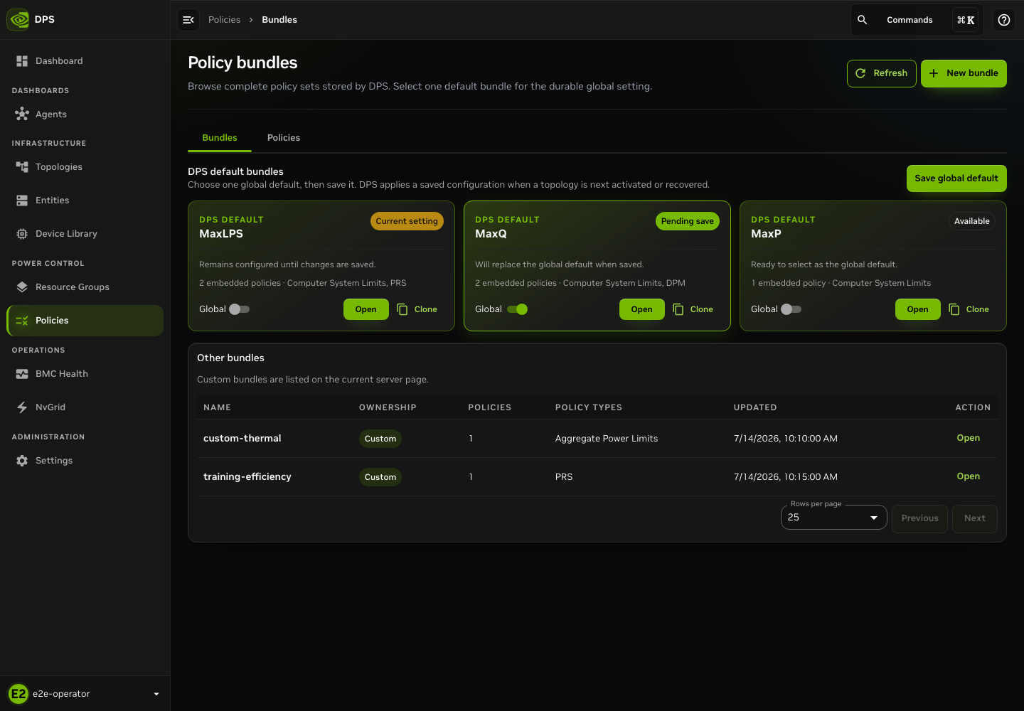
MaxLPS remains the current setting until you save. MaxQ is the staged replacement.
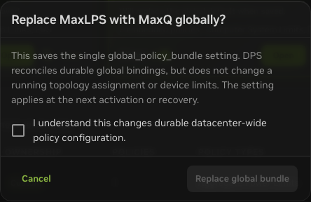
Replacing the default requires acknowledgment of a durable configuration change used for future empty bundle selections.
When no global default exists, selecting a default creates an initial configuration confirmation.
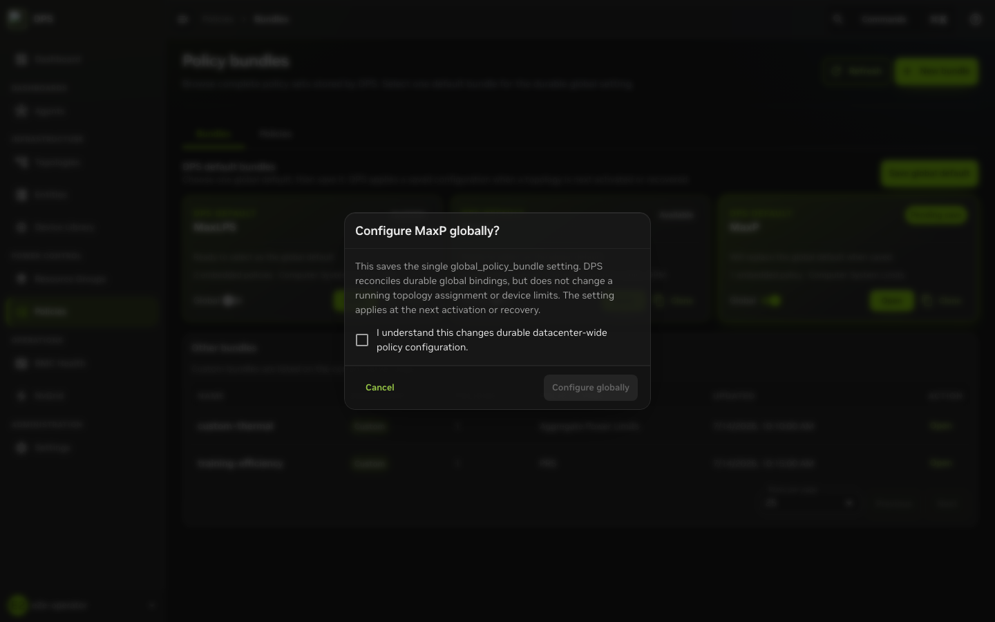
Initial MaxP selection. The same setting and lifecycle boundary applies to every default bundle.
To remove a configured global default, turn off the current bundle Global
switch and then select Save global default. DPS receives
an empty global_policy_bundle setting only after you acknowledge the removal
confirmation.
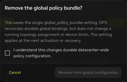
Removing the global default changes durable configuration. Active topology and device state are unaffected.
If a save fails or the readback does not preserve the selected value, the UI
reports an error. Do not assume the bundle is configured. Refresh and inspect
the returned state. If the stored global_policy_bundle is malformed, the
default-card controls remain disabled until DPS returns a
valid setting. Use the approved recovery path to correct the configuration.
A configured global default shows which configuration is selected. It does not mean that DPS reactivated an existing topology or applied the policy to a device.
Create and Activate a Resource Group#
A resource group combines member resources, a policy-bundle selection, priority, and optional metadata. Resource-group changes can affect allocation outcomes. Use a staged workflow.
Create the Group and Select Members#
Use these steps to create a resource group.
Open Resource Groups and select New resource group.
Enter a unique group name. Select a policy bundle explicitly or leave it unset to resolve and persist the current
global_policy_bundle. An unset value does not categorically mean “inherit the topology policy.”Add members from the active topology or enter exact resource names. Review overlap messages. A resource cannot belong to more than one active resource group at a time.
Review priority and advanced metadata before you select Create group.
After creation, open the group Overview. Start with the Readiness checklist, which reports membership, policy, capability, and operator-budget context before lifecycle action.
The current server does not support changing a resource group’s policy-bundle selection through an update. Select the required bundle when creating the group.
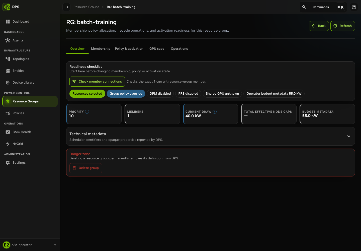
Readiness for the inactive batch-training group. Review this state
before you edit membership or activation options.
Validate Allocation Before Activation#
Open Policy & activation and select Validate allocation. This is the preflight for current membership, selected policy, and activation guards. Validate again after you change any supported input.
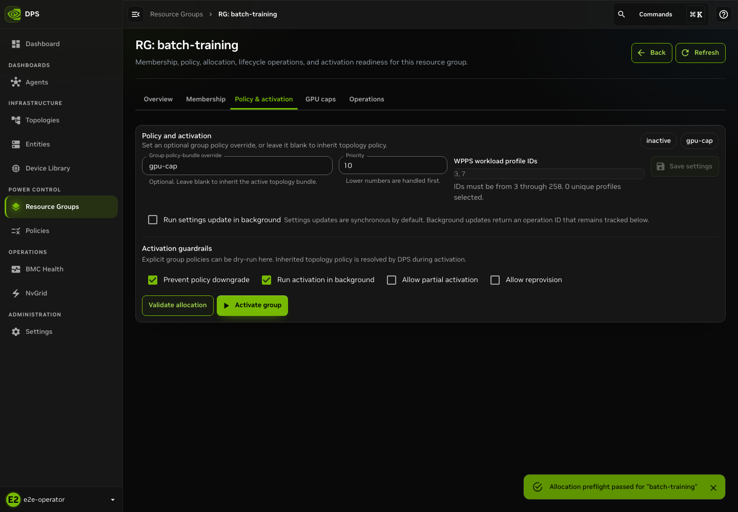
A successful preflight enables the next guarded action. Activation is separate.
Select Activate group only after you understand the preflight and allocation impact. The confirmation describes how activation can change resource-group power allocations. Acknowledge it only with the required operational approval.
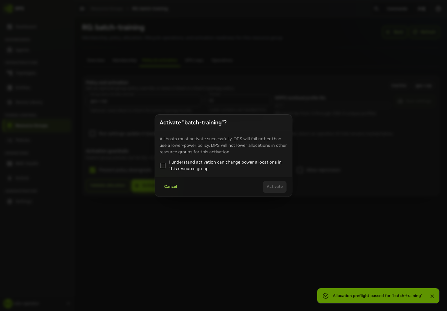
Activation requires explicit acknowledgment. Retain approved partial-activation and reprovisioning safeguards unless the operational plan requires a change.
Track the result in the resource-group Operations section. A task ID or a request acknowledgment does not prove that every resource accepted its policy. Review the returned per-resource status.
Inspect Operational Views#
Use operational views to investigate and verify current state. They do not replace the result of a write, topology lifecycle operation, or resource-group operation.
Entities and Device Templates#
Open Entities to inspect active-topology inventory. Live node status requests the latest status data. Use runtime-health filters to focus the investigation. Inspect a row for entity details, effective policy context, and related resource-group information.
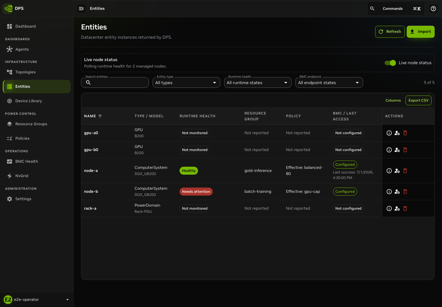
Entity inventory with live-status information enabled.
Use Device Library to inspect registered device-template definitions, including supported component and management information. Device templates are inventory definitions. Changing one is a separate write workflow that requires review before import or replacement.
BMC Health Reports#
DPS 0.9 requires the selected topology to be active before starting a BMC health check, including in Read-only mode. Follow Managing Topologies to activate the topology before running this diagnostic.
Open BMC Health for report-oriented diagnostics. Prefer Read-only mode for endpoint and prerequisite evidence. Start a check only after you confirm the topology and node scope. Retain the returned task ID. Review the cluster summary, latency distributions, issues, and node-specific detail.
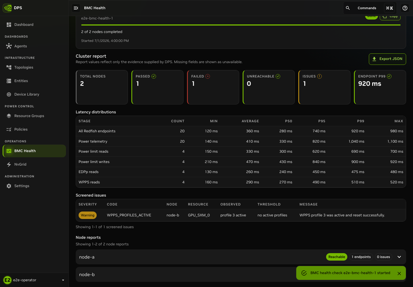
Read-only report. Missing information is not evidence of health.
Deep BMC probes can exercise temporary power-limit writes. They have additional side effects and are outside this read-only procedure. Use a deep probe only with the documented approval and recovery plan.
Agents, Allocation, NvGrid, and Settings#
Use these views for read-only inspection.
Agents shows current agent information and assignments.
Allocation shows capacity, draw, and resource-group allocation context. This context is not a prediction that a pending activation succeeds.
NvGrid shows feeds, current targets, and scheduled targets. Inspect the affected feeds and timing before you consider a target or webhook mutation.
Settings shows the connected server and deployment settings. Any save is system-wide and requires review.
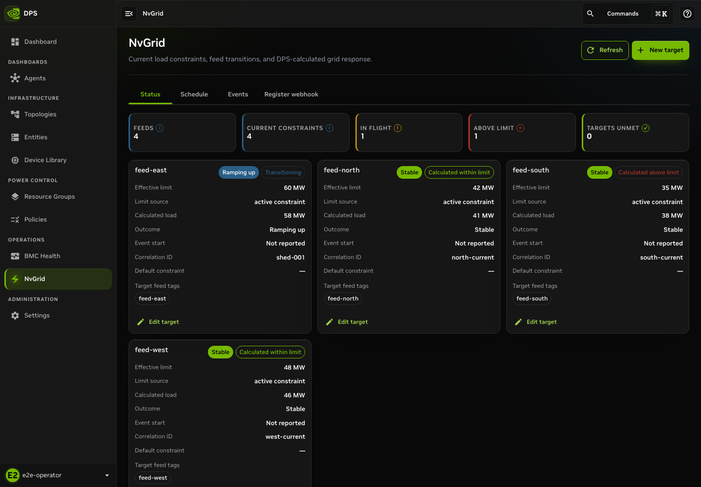
NvGrid feed status for the example deployment.
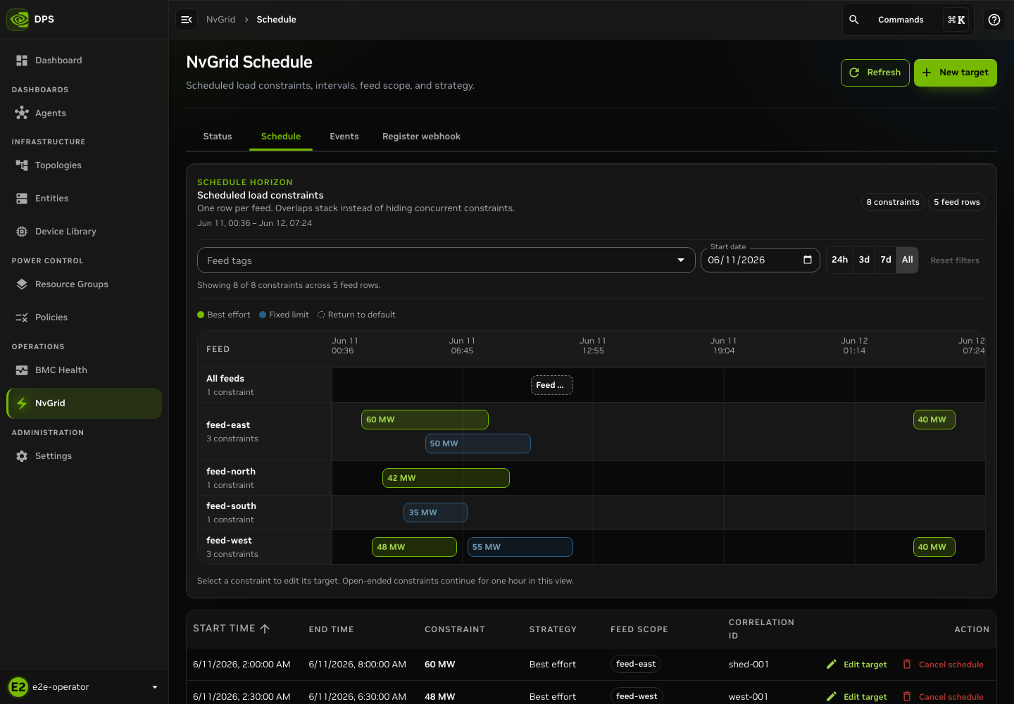
NvGrid schedule. Review target timing and affected feeds before you plan an operational change.
Identify Deployment and BMC Issues#
Use this procedure to collect evidence and route an issue to the owning team. It does not replace site change control, BMC break-fix procedures, or the result that DPS returns for a lifecycle operation.
Triage Deployment and Access Issues#
Start with Settings > Deployment. The DPS server card shows the server-reported version, commit, build date, and last refresh.
Select Refresh when an expected version or build is absent. The UI retains the last successful response. It identifies a failed refresh rather than treating stale information as current.
Select Run verification to request the deployment readiness check. Record each reported component separately.
Reported Component |
Record |
Initial Routing |
|---|---|---|
DPS server |
Status, message, server version, commit, and build date. |
DPS service owner. |
Database |
Status and returned diagnostic. |
DPS data-service owner. |
Authentication |
Status and sign-in error, without tokens, callback values, or cookies. |
Identity and authentication owner. |
UI |
Status and affected page or route. |
UI deployment owner. |
BCM |
Status, Skipped, or Not reported result. |
BCM or infrastructure owner when BMC management is expected. |
Action required means that DPS reported at least one unhealthy component. Incomplete, Skipped, and Not reported are not healthy results. They show that the check did not return a complete component result.
Do not use an optional BCM result alone to decide that a node BMC is healthy.
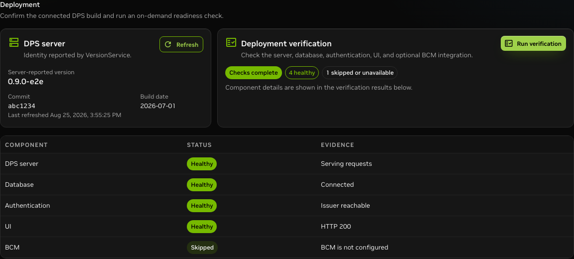
The example shows version identity, four healthy components, and an explicitly skipped optional BCM integration. Treat each result as triage input, not as a generic deployment-health claim.
For a sign-in failure, retain the visible error and affected UI URL without its query string. Verify the identity provider and expected role before retrying.
Do not include authorization codes, state values, refresh data, bearer
tokens, cookies, or passwords in a ticket, chat, image, or exported log.
For an authenticated page that cannot load DPS data, record the route, visible error, time and time zone, and deployment-verification state before you retry. A page-level error can result from access control, service availability, or an unavailable upstream dependency.
Do not diagnose the cause from a browser status alone. Avoid Save, Import, activation, and other write controls while you collect failure evidence.
Start BMC Triage from Dashboard Attention#
The dashboard Needs attention area and the BMC Health navigation item provide an operational starting point. A baseboard management controller (BMC) result comes from a node report, not from the dashboard. Select BMC Health to start a diagnostic workflow. If your deployment presents Open BMC health for a BMC- or telemetry-related item, use that action. Start the check in Read-only mode and retain its task ID. The resulting report records which selected nodes were reachable and which checks failed.
Dashboard triage entry point. The red agent-east-2 item reports a
disconnected agent and missing device reports. It does not show that a BMC is
unreachable. Use Operations > BMC Health to collect a read-only report.
An Agent fleet warning is important context, but it does not prove that a node BMC is unavailable. Review the agent assignment and telemetry path, then use the BMC Health report to distinguish agent or data-path coverage from BMC endpoint evidence. A missing telemetry reading is also not a BMC failure by itself. Do not activate a topology, change a policy, or run a deep probe only because the dashboard contains an attention item.
Diagnose a BMC Issue Safely#
Use this read-only procedure first.
Open BMC Health. Select the topology and node scope. Retain Read-only, which tests endpoints without the deep-probe temporary power-limit changes.
Start the check and retain its task ID. If another operator started it, use Report access > Server task or enter the known Task ID. This attaches to the existing report instead of starting a duplicate probe.
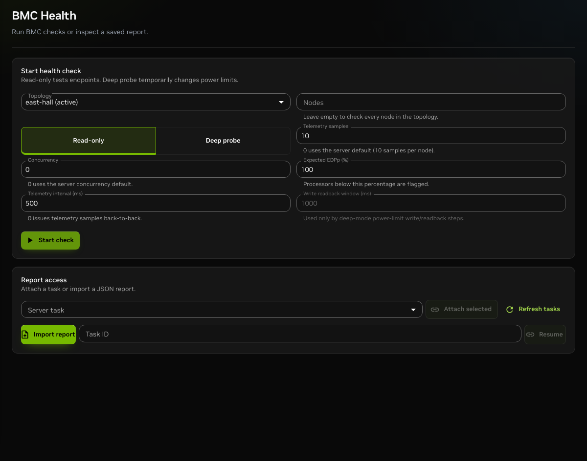
Initial diagnostic screen. Select scope, retain Read-only, and either start a check or attach to an existing task. Do not use a deep probe as the default troubleshooting action.
In Cluster report, separate task or report availability from node findings. An unavailable task or report identifies a task-retention issue. Failures and unreachable counts describe evidence from selected nodes.
Review Latency distributions by stage. Compare count, average, p95, p99, and maximum with a known-good run in the same environment. Do not use a universal latency threshold. Endpoint or telemetry latency requires correlation with BMC, network, and agent telemetry. It does not prove a root cause.
Use Screened issues to identify the node, resource, observed value, threshold, and DPS message. Open the matching Node report for firmware, endpoint data, power-setting evidence, Electrical Design Point (EDPp) settings, Workload Power Profiles Settings (WPPS), and telemetry detail.
Export report JSON and retain the task ID before escalation. Include only relevant node names and diagnostics. Remove credentials, IP-address details, and other sensitive site data according to the incident process.
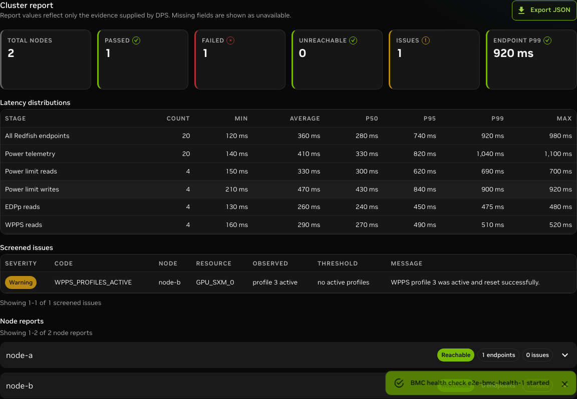
Report with a failed node and a screened WPPS issue. Use the node report to separate an observed symptom from a diagnosis.
Warning
Do not use Deep probe as a harmless retry. It can temporarily change power limits. Setpoint restoration is best effort. The probe can disable active WPPS profiles and does not restore them automatically.
Run a deep probe only with a site-approved maintenance window, scope, rollback plan, and authorization.
Operator Checklist#
Before you start a write or lifecycle action, confirm these items.
The selected topology, resource group, policy bundle, or task is the intended object.
The UI shows the expected DPS readback and no unresolved error.
You ran validation after the final edit.
The confirmation text matches the intended operational scope.
A follow-up view or operation result confirms what DPS accepted.