

Overview#
This guide provides instructions for creating and managing Power Distribution Network (PDN) topology through the Dynamic Power Software (DPS) user interface. While topology entities and relationships can be defined manually through configuration files as described in the PDN Diagrams guide, the web-based user interface provides an intuitive graphical approach for both creating topology entities and managing their relationships.
Note: The examples and procedures in this guide will create the same topology structure and entities as demonstrated in the PDN Diagrams guide. Both approaches result in identical topology configurations, allowing you to choose the method that best suits your workflow: graphical UI or configuration files.
Benefits of UI-Based Topology Management#
Using the user interface for topology management offers several advantages:
Visual Representation: See the power distribution hierarchy in a graphical format
Ease of Use: No need to manually edit configuration files
Error Prevention: Built-in validation prevents common configuration mistakes
Collaborative Editing: Multiple administrators can work on topology configurations
Getting Started#
Prerequisites#
Deployed DPS system
Web browser with JavaScript enabled
Understanding of datacenter power distribution concepts
Accessing the UI#
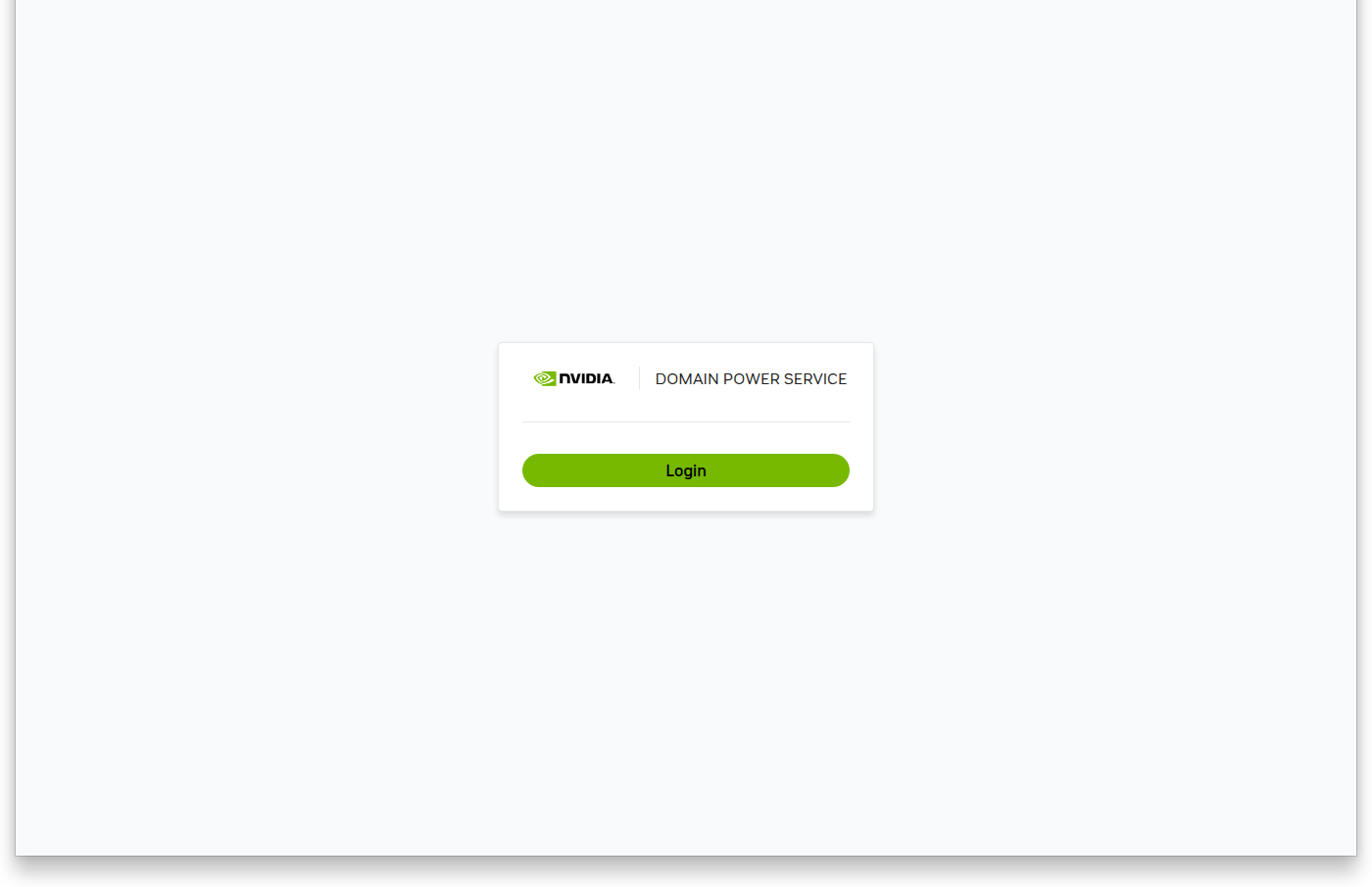
In the DPS SDK environment, the user interface is available at:
URL: http://ui.dps.sdk
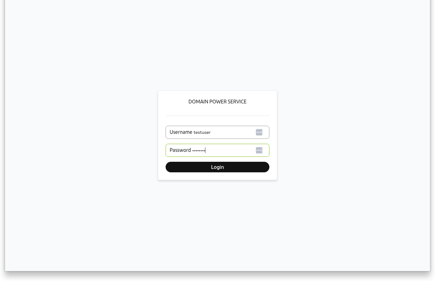
Authentication:
Username:
dpsPassword:
dps
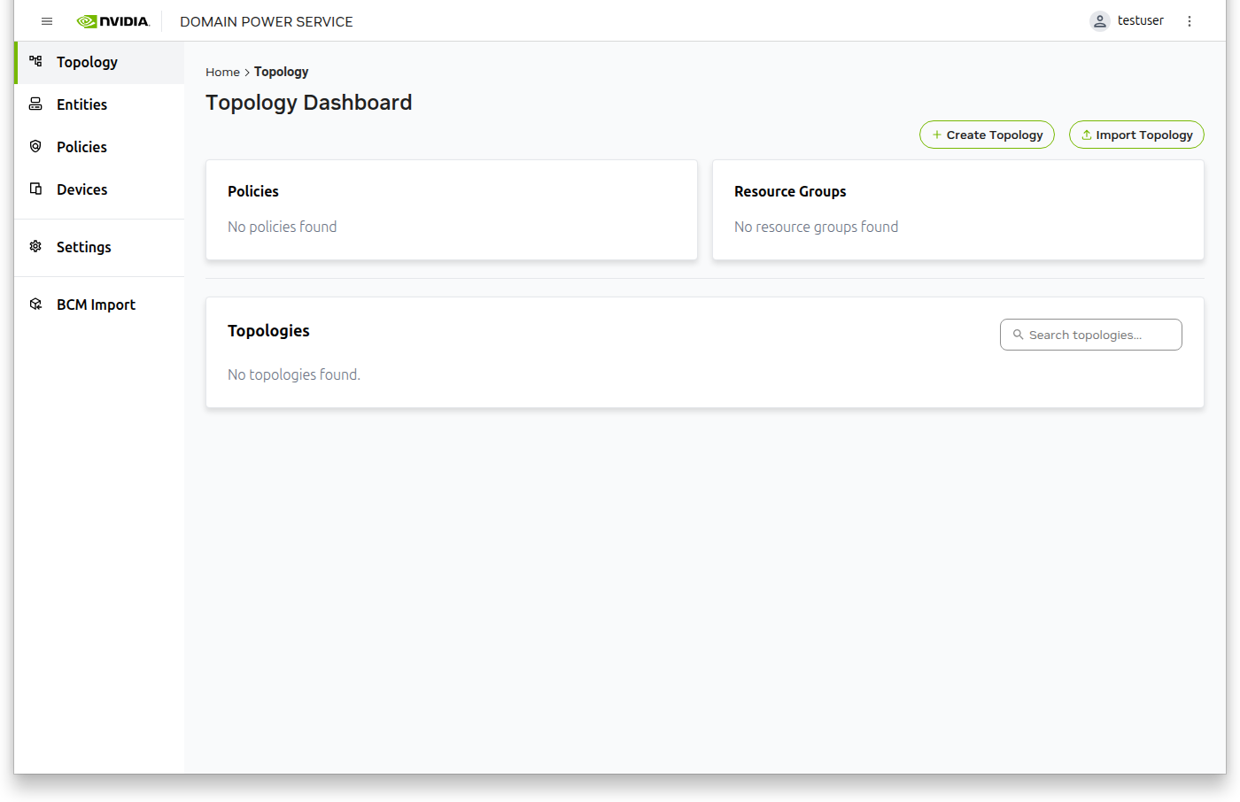
Topology Creation#
Creating a topology involves several sequential steps: defining policies, optionally importing custom devices, creating entities, building the topology structure with their relationships, and finally activating it.
Step 1: Create Policies#
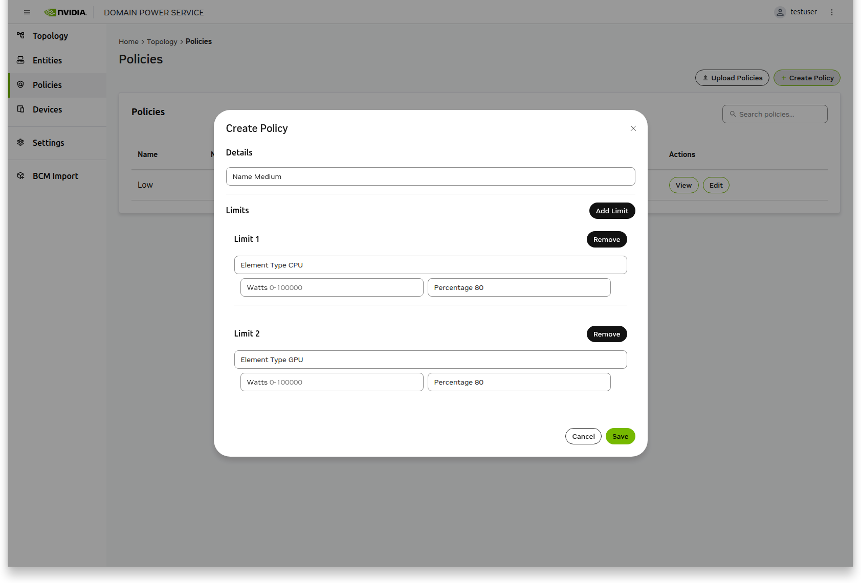
Before creating a topology, you must first define the policies that will govern power limits.
Select Policies from the left navigation panel
Click the Create Policy button
Specify a policy name
Click Add Limit to define power constraints
Multiple limits can be added, one per element type
Limits can be specified in either Watts or Percentage
Click Save to store the policy
Repeat these steps for each additional policy you need
Step 2: Import Custom Devices (Optional)#
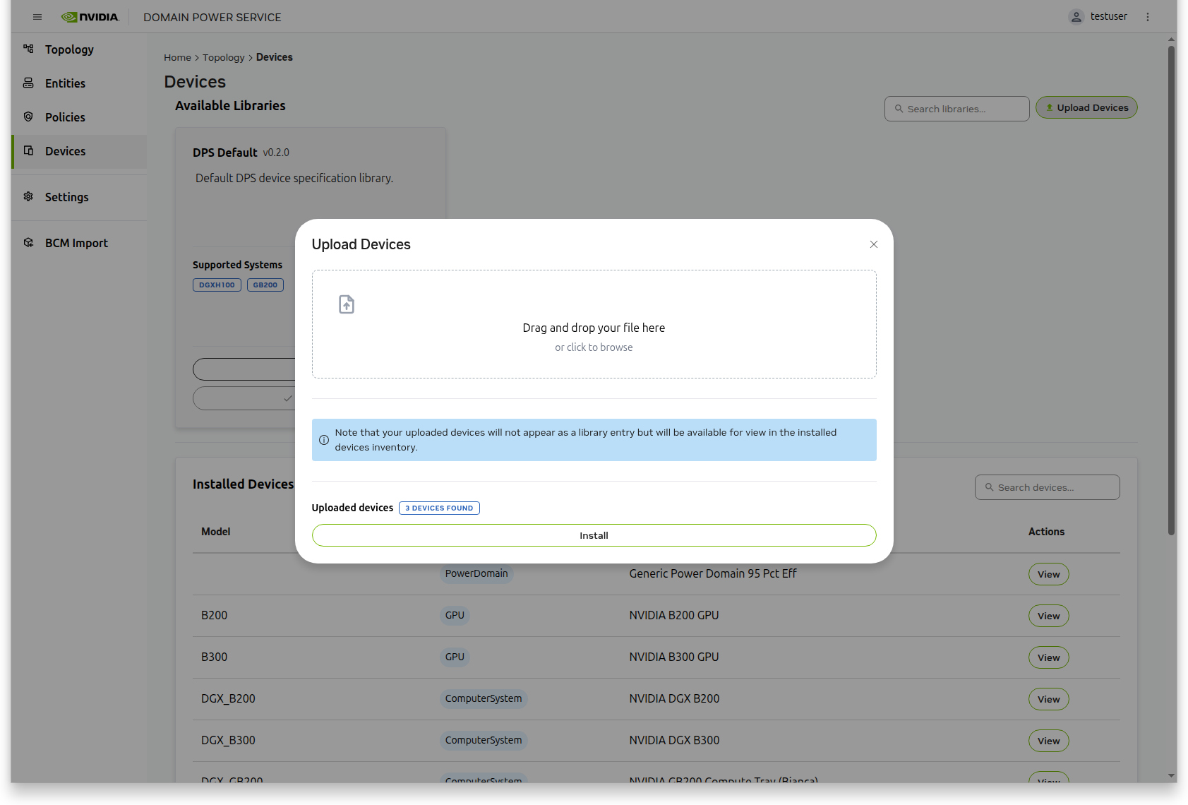
If any of your entities require custom device specifications, you must import those devices before creating entities. The UI does not support defining custom devices directly through a form.
Select Devices from the left navigation panel
Click Upload Devices
Choose your device specification YAML file
The devices will be imported and available for use in entity creation
For examples of device specification YAML files and instructions on how to create them, refer to the Add Custom Device Specifications section in the PDN Diagrams guide.
Step 3: Create Entities#
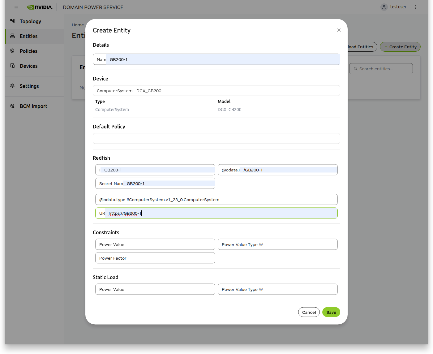
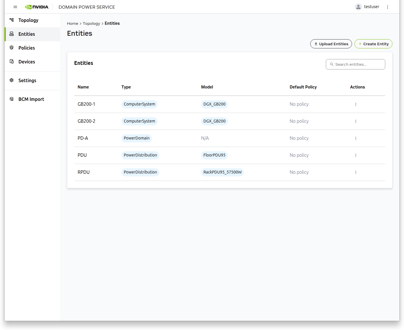
With policies defined and any required custom devices imported, you can now create the entities that represent your power distribution components.
Select Entities from the left navigation panel
Click the Create Entity button
Fill in the entity details
Click Save
Repeat these steps for each entity in your topology
Step 4: Build and Configure the Topology#
With policies and entities defined, you can now construct your topology and define the relationships between entities. This is done in a single continuous workflow within the topology builder.
Add Entities to the Topology#
Navigate to Topology in the left navigation panel
Click Create Topology
In the dialog window, click Add Entities
Select all entities from the previous step
Click Add Selected Entities
The topology builder will populate with your selected entities
Define Entity Relationships#
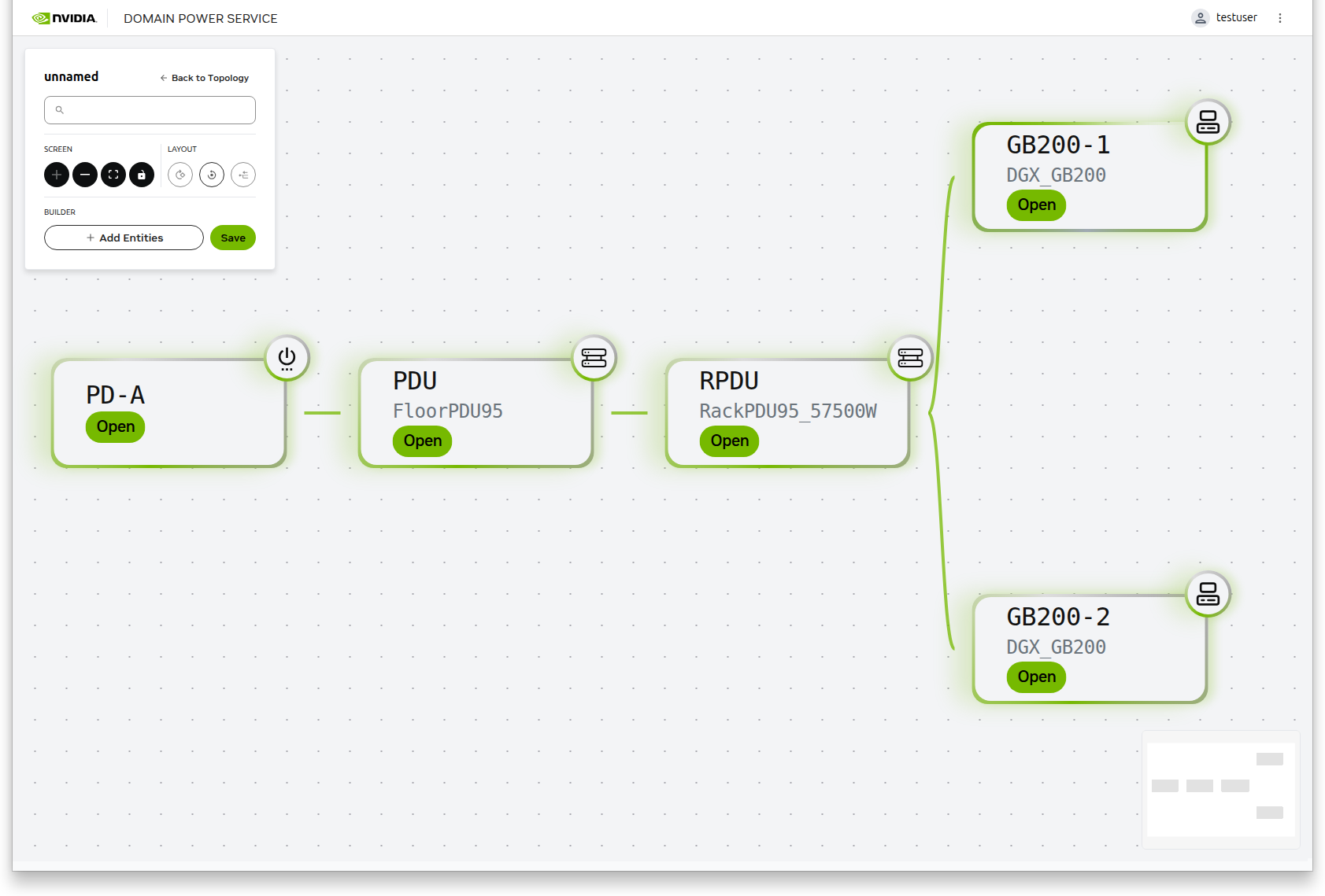
Configure the hierarchical relationships between entities using the interactive builder.
The builder automatically enters interactive mode after adding entities
Drag entities close to each other to create connections
Parent-Child Hierarchy: The leftmost item in a connection is the parent; the rightmost item is the child
Position determines the power distribution flow through your topology
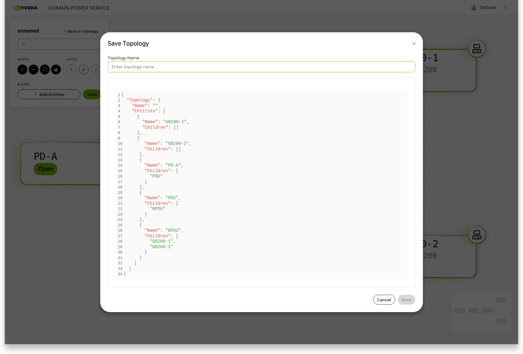
Once all relationships are established, click Save
Specify a topology name in the save dialog
Review the generated topology JSON displayed at the bottom of the dialog
Click Save to create your topology
Tip: To prevent undesired connection lines from being created accidentally, space entities wider apart before dragging them to create intentional connections. This gives you better control over which entities connect to each other.
Step 5: Activate the Topology#
After creating your topology, activate it to make it operational.
Navigate to Topology in the left navigation panel to view the Topologies list
Locate your newly created topology
Select Activate from the Actions column
Note: Only one topology can be active at a time. Activating a new topology will automatically deactivate any previously active topology.