Using the BMC#
The NVIDIA DGX A100 system comes with a baseboard management controller (BMC) for monitoring and controlling various hardware devices on the system. It monitors system sensors and other parameters.
Connecting to the BMC#
Here are the steps to connect to the BMC on a DGX A100 system.
Before you begin, ensure that you have connected the BMC port on the DGX A100 system to your LAN.
Open a browser within your LAN and go to
https://<bmc-ip-address>/.The BMC is supported on the following browsers:
Internet Explorer 11 and later
Firefox 29.0 (64-bit) and later
Google Chrome 7.0.3396.87 (64-bit) and later
Log in.
The BMC dashboard opens.
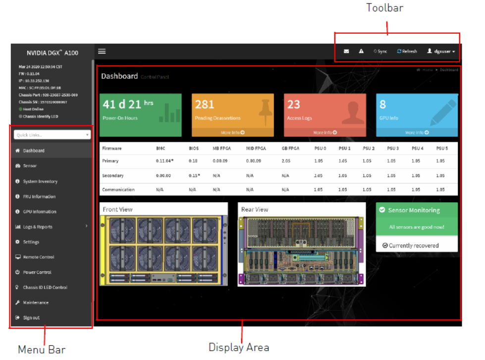
Overview of BMC Controls#
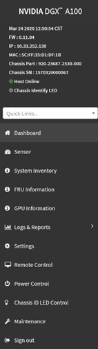
The left-side navigation menu bar on the BMC main page contains the primary controls.
Control |
Description |
|---|---|
Quick Links |
Provides quick access to several tasks. |
Dashboard |
Displays the overall information about the status of the device. |
Sensor |
Provides status and readings for system sensors, such as SSD, PSUs, voltages, CPU temperatures, DIMM temperatures, and fan speeds. |
System Inventory |
Displays inventory information of system modules. |
FRU Information |
System, Processor, Memory Controller, BaseBoard, Power, Thermal, PCIE Device, PCIE Function, and Storage. |
GPU Information |
Provides basic information on all the GPUs in the systems, including GUID, VBIOS version, InfoROM version, and number of retired pages for each GPU. |
Logs and Reports |
View, and if applicable, download and erase, the IPMI event log, and System, Audit, Video, and POST Code logs. |
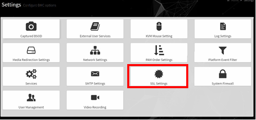
Settings |
Configure the following settings: Captured BSOD, External User Services, KVM Mouse Setting, Log Settings, Media Redirection Settings, Network Settings, PAM Order Settings, Platform Event Filter, Services, SMTP Settings, SSL Settings, System Firewall, User Management, and Video Recording |
Remote Control |
Opens the KVM Launch page to remotely access the DGX A100 console. |
Power Control |
Perform the following power actions: Power On, Power Off, Power Cycle, Hard Reset, and ACP/Shutdown |
Chassis ID LED Control |
Lets you to change the chassis ID LED behavior: Off, Solid On, Blinking On (select from 5 to 255 second blinking intervals). |
Maintenance |
Perform the following maintenance tasks: Backup Configuration, Firmware Image Location, Firmware Update, Preserve Configuration, Restore Configuration, Restore Factory Defaults, and System Administrator |
Sign out |
Sign out of the BMC web UI. |
Common BMC Tasks#
This section provides information about the most common BMC tasks.
Changing the BMC Login Credentials#
Here is information about how you can add or remove users.
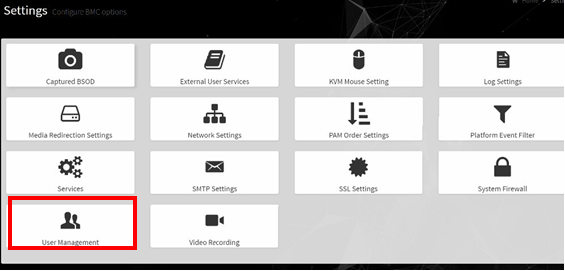
Select Settings from the left-side navigation menu.
Select the User Management card.
Click the Help icon (?) for information about configuring users and creating a password.
Log out and then log back in with the new credentials.
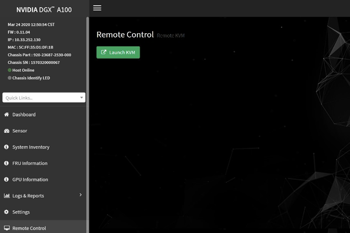
Using the Remote Console#
Here is some information about how to log in to the remote console.
Click Remote Control from the left-side navigation menu.
Click Launch KVM to start the remote KVM and access the DGX A100 console.
Setting Up Active Directory or LDAP/E-Directory#
Here is some information about how you can set up Active Directory or LDAP/E-Directory.
From the side navigation menu, click Settings > External User Services.
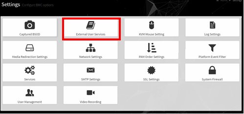
Click Active Directory Settings or LDAP/E-Directory Settings and follow the instructions.

LDAP/E-Directory Settings#
Setup the BMC for external authentication and authorization using LDAP.
Configure the General Settings
The configuration for the General LDAP/E-Directory Settings can be straightforward if you know the details about your LDAP service.

Configuring LDAP to use an Active Directory server is supported. Contact your Active Directory administrator to configure the LDAP details and help with any troubleshooting that may be necessary. Windows server firewall rules may be blocking external connections to the default LDAP ports 389 and 636.
Authoritative Bind to the LDAP service is required, meaning this cannot be configured with anonymous bind. The Bind DN and Password fields are the bind credentials and are used for every lookup. The bind process is the BMC authenticating itself as a valid endpoint, before it can perform any lookup.
The Search Base and Attribute of User Login are used to convert the BMC login
usernamestring to a DN string that the LDAP server expects.Click Save to validate and store the LDAP settings.
If you revisit this page, you will have to re-enter the Password field.
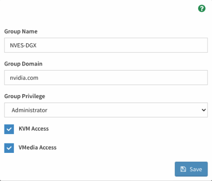
Configure Role Groups.
The Role Groups must be configured to assign BMC permissions to the authenticated user, otherwise known as authorization. This is done by mapping an LDAP group membership to BMC permissions.
If you do not create a role group mapping, authentication fails, because the user would not have any permissions in the BMC interface.
To add a Role Group, click on one of the cards.
Specify the LDAP group name and group domain to map to the BMC privilege level/permissions. If you are unsure about the settings, contact the LDAP administrator for help.
The Group Domain field corresponds to the group search base DN for the group name lookup.
The LDAP group filter used by the BMC is not configurable. The pre-configured group filter searches for the group name, CN, with objectClass matching “groupOfNames” or “group”.
filter="(&(|(objectClass=groupOfNames)(?objectClass=group))(cn=dgx_admins))"Therefore, the LDAP service group structure MUST use either of the following:
LDAP standard (rfc2256) structural objectClass “groupOfNames”, with the member attributes specifying the users assigned to the group.
Align with Active Directory structure using objectClass “group”.
Save the configuration and start authenticating using valid LDAP credentials.
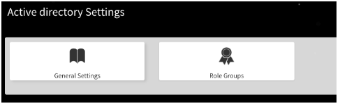
Active Directory Settings#
Setup the BMC for external authentication and authorization using Active Directory.
Configure the General Settings
The configuration for the Active Directory can be straightforward if you know the details about your Active Directory cluster.
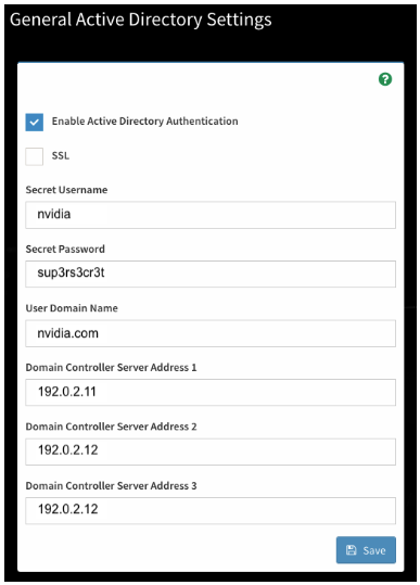
If you are unsure about the settings, contact the AD administrator for help. You may require an AD admin account to connect the BMC to the AD forest.
The User Domain Name field must match all or part of the BMC domain name. If the BMC is in a subdomain, such as bmc.nvex.nvidia.com, then the User Domain Name could be set to the subdomain, nvex.nvidia.com, or the parent domain, nvidia.com.
Note
Authentication across domains requires the proper AD trust relationship. For more information, refer to Pass-Through Authentication and Domain Trusts in the Microsoft documentation.
Click Save to validate and store the AD settings. If you revisit this page, you need to re-enter the Secret Password field.
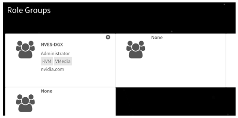
Configure Role Groups
The Role Groups must be configured to assign BMC permissions to the authenticated user, otherwise known as authorization. This is done by mapping Active Directory group membership to BMC permissions.
If you do not configure a role group mapping, authentication fails, because the user would not have any permissions in the BMC interface.
To add a Role Group, click on one of the cards.
Specify the AD group name and group domain to map to the BMC privilege level/permissions. If you are unsure about the settings, contact the AD administrator for help.
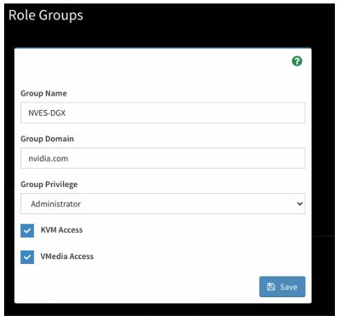
Save the configuration and start authenticating using valid AD credentials.
Configuring Platform Event Filters#
From the side navigation menu, click Settings and click Platform Event Filters.
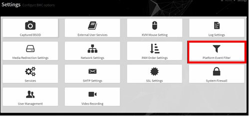
The Event Filters page shows all configured event filters and available slots. You can modify or add new event filter entry on this page.
To view available configured and unconfigured slots, click All in the upper-left corner of the page.
To view available configured slots, click Configured in the upper-left corner of the page.
To view available unconfigured slots, click UnConfigured in the upper-left corner of the page.
To delete an event filter from the list, click the x icon.
Uploading or Generating SSL Certificates#
You can set up a new certificate by generating a (self-signed) SSL or by uploading an SSL (for example, to use a Trusted CA-signed certificate).
From the side navigation menu, click Settings > External User Services.
Refer to the following sections for more information:
Viewing the SSL Certificate#
To view the SSL certificate, on the SSL Setting page, click View SSL Certificate.
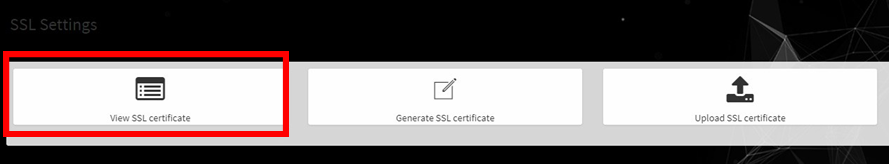
The View SSL Certificate page displays the following basic information about the uploaded SSL certificate:
Certificate Version, Serial Number, Algorithm, and Public Key
Issuer information
Valid Date range
Issued to information
Generating the SSL Certificate#
Here is some information about generating an SSL certificate.
Context for the current task.
From the SSL Setting page, select Generate SSL Certificate.
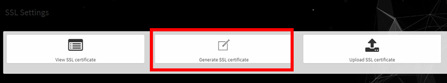
Enter the information as described in the following table.
Generate SSL Certificate# Items
Description/Requirements
Common Name (CN)
The common name for which the certificate is to be generated.
Maximum length of 64 alphanumeric characters.
Special characters ‘#’ and ‘$’ are not allowed.
Organization (O)
The name of the organization for which the certificate is generated.
Maximum length of 64 alphanumeric characters.
Special characters ‘#’ and ‘$’ are not allowed.
Organization Unit (OU)
Overall organization section unit name for which the certificate is generated.
Maximum length of 64 alphanumeric characters.
Special characters ‘#’ and ‘$’ are not allowed.
City or Locality (L)
City or Locality of the organization (mandatory)
Maximum length of 64 alphanumeric characters.
Special characters ‘#’ and ‘$’ are not allowed.
State or Province (ST)
State or Province of the organization (mandatory)
Maximum length of 64 alphanumeric characters.
Special characters ‘#’ and ‘$’ are not allowed.
Country (C)
Country code of the organization.
Only two characters are allowed.
Special characters are not allowed.
Email Address
Email address of the organization (mandatory)
Valid for
Validity of the certificate.
Key Length
Enter a range from 1 to 3650 (days)
Click Save to generate the new certificate.
Uploading the SSL Certificate#
Make sure the certificate and key meet the following requirements:
SSL certificates and keys must both use the .pem file extension.
Private keys must not be encrypted.
SSL certificates and keys must each be less than 3584 bits in size.
SSL certificates must be current (not expired).
On the SSL Setting page, click Upload SSL Certificate.
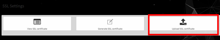
Click the New Certificate folder icon, browse to locate the appropriate file, and select it.
Click the New Private Key folder icon, browse and locate the appropriate file, and select it.
Click Save.
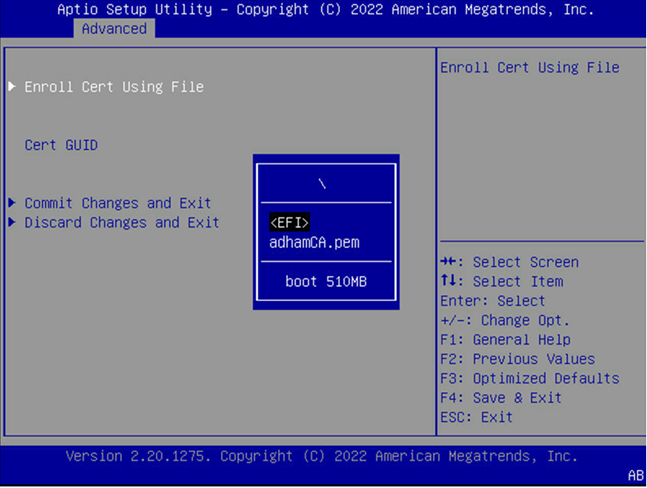
Updating the SBIOS Certificate#
The CA Certificate for the trusted CA that was used to sign the SSL certificate must be uploaded to allow the SBIOS to authenticate the certificate.
Obtain the CA certificate from the signing authority that was used to sign the SSL certificate.
Copy the CA certificate onto a USB thumb drive or to /boot/efi on the A100 OS.
Access the DGX A100 console from a locally connected keyboard and mouse or through the BMC remote console.
Reboot the server
To enter BIOS setup menu, when prompted, press DEL.
In the BIOS setup menu on the Advanced tab, select Tls Auth Config.
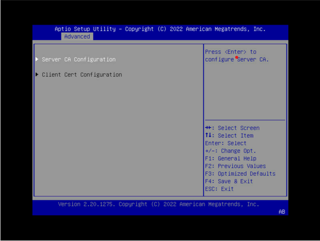
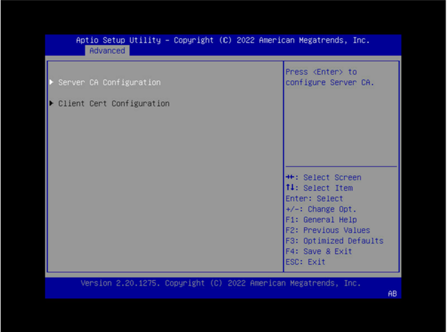
Select Server CA Configuration.
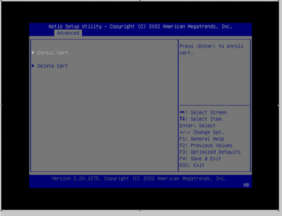
Select Enroll Cert.
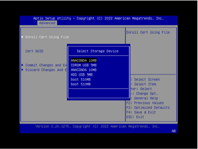
Select Enroll Cert Using File.
Select the device where you stored the certificate.
Navigate the file structure and select the certificate.