Introduction to the NVIDIA DGX A100 System#
The NVIDIA DGX™ A100 System is the universal system purpose-built for all AI infrastructure and workloads, from analytics to training to inference. The system is built on eight NVIDIA A100 Tensor Core GPUs.

This document is for users and administrators of the DGX A100 system.
Hardware Overview#
This section provides information about the hardware in DGX A100.
DGX A100 Models and Component Descriptions#
There are two models of the NVIDIA DGX A100 system: the NVIDIA DGX A100 640GB system and the NVIDIA DGX A100 320GB system.
Model Differentiation#
Component |
NVIDIA DGX A100 640GB System |
NVIDIA DGX A100 320GB System |
|---|---|---|
GPU |
Qty 8 NVIDIA A100 GPUs Third-generation NVLinks |
Qty 8 NVIDIA A100 GPUs Third-generation NVLinks |
Total GPU Memory |
640 GB |
320 GB |
NVIDIA NVSwitch |
Qty 6 Second generation (2x faster than first generation) |
Qty 6 Second generation (2x faster than first generation) |
Networking |
Up to 10 (Factory ship config) NVIDIA ConnectX-6 or ConnectX-7 InfiniBand/200 Gb/s Ethernet |
Up to 9 (Factory ship config) NVIDIA ConnectX-6 or ConnectX-7 IB/200 Gb/s Ethernet (Optional Add-on: Second dual- port 200 Gb/s Ethernet) |
CPU |
2 AMD Rome, 128 cores total |
2 AMD Rome, 128 cores total |
System Memory |
2 TB (Factory ship config) |
1 TB (Factory ship config) (Optional Add-on: 1 TB to get 2 TB max.) |
Storage |
30 TB (Factory ship config) U.2 NVMe Drives (Optional drive upgrade to 60 TB) |
15 TB (Factory ship config) U.2 NVMe Drives (Optional Add-on: 15 TB to get 30 TB max. Optional drive upgrade to 60 TB) |
Component Description#
Component |
Description |
|---|---|
GPU |
NVIDIA A100 GPU |
CPU |
2x AMD EPYC 7742 CPU w/64 cores |
NVSwitch |
600 GB/s GPU-to-GPU bandwidth |
Storage (OS) |
1.92 TB NVMe M.2 SSD (ea) in RAID 1 array |
Storage (Data Cache) |
3.84 TB NVMe U.2 SED (ea) in RAID 0 array (Optional 7.68 TB NVMe U.2. SEDs) |
Network (Cluster) card |
NVIDIA ConnectX-6 or ConnectX-7 Single Port InfiniBand (default): Up to 200Gbps Ethernet: 200GbE, 100GbE, 50GbE, 40GbE, 25GbE, and 10GbE Note NVIDIA ConnectX-7 Single-Port network cards support InfiniBand protocol only. |
Network (Storage) card |
NVIDIA ConnectX-6 or ConnectX-7 Dual Port Ethernet (default): 200GbE, 100GbE, 50GbE, 40GbE, 25GbE, and 10GbE InfiniBand: Up to 200Gbps |
System Memory (DIMM) |
1 TB per 16 DIMMs |
BMC (out-of-band system management) |
1 GbE RJ45 interface Supports IPMI, SNMP, KVM, and Web user interface, and Redfish APIs. |
In-band system management |
1 GbE RJ45 interface |
Power Supply |
3 kW |
Mechanical Specifications#
Here is some information about mechanical specifications.
Feature |
Description |
|---|---|
Form Factor |
6U Rackmount |
Height |
10.4” (264 mm) |
Width |
19” (482.3 mm) max |
Depth |
35.3” (897.1 mm) max |
System Weight |
271.5 lbs (123.16 kg) max |
Power Specifications#
The DGX A100 system contains six power supplies with balanced distribution of the power load.
Input |
Specification for Each Power Supply |
|
|---|---|---|
200-240 volts AC |
6.5 kW max. |
3000 W @ 200-240 V, 16 A, 50-60 Hz |
Support for N+N Redundancy#
The DGX A100 includes six power supply units (PSU) configured for 3+3 redundancy. If three PSUs fail, the system will continue to operate at full power with the remaining three PSUs.
Note
If only two PSUs are working, the GPUs will not be available but the server will still boot. This is to allow you to gather debug or system logs or other data from the cache SSDs.
If only one PSU is working, troubleshoot the cause for the loss of power from the other PSUs and correct. If faulty PSUs need to be replaced, shut the system down and install working PSUs.
DGX A100 Locking Power Cord Specification#
The DGX A100 is shipped with a set of six (6) locking power cords that have been qualified for use with the DGX A100 to ensure regulatory compliance.
The following locking power cord types are approved:
Switch-locking for the PSU side
Twist-locking for the PSU side
Warning
To avoid electric shock or fire, only use the NVIDIA-provided power cords to connect power to the DGX A100. For more details, see Electrical Precautions.
Important
Do not use the provided cables with any other product or for any other purpose.
Power Cord Specification#
Power Cord Feature |
Specification |
|---|---|
Electrical |
250VAC, 16A |
Plug Standard |
C19/C20 |
Dimension |
1200mm length |
Compliance |
Cord: UL62, IEC60227 Connector/Plug: IEC60320-1 |
Using the Locking Power Cords#
This section provides information about how to use the locking power cords.
Locking and Unlocking the PDU Side#
Power Distribution Unit side
To INSERT, push the cable into the PDU socket.
To REMOVE, press the clips together and pull the cord out of the socket.
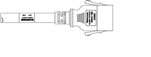
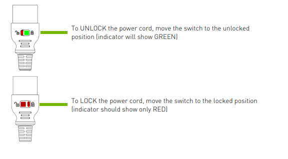
Locking/Unlocking the PSU Side (Cords with Switch-Lock Mechanism)#
Power Supply (System) side - Switch locking
To INSERT or REMOVE make sure the cable is UNLOCKED and push/ pull into/out of the socket.
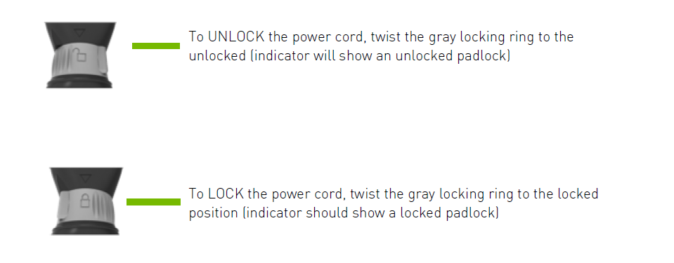
Locking/Unlocking the PSU Side (Cords with Twist-Lock Mechanism)#
Power Supply (System) side - Twist locking
To INSERT or REMOVE make sure the cable is UNLOCKED and push/ pull into/out of the socket.
Environmental Specifications#
Here are the environmental specifications for your DGX A100 system.
Feature |
Specification |
|---|---|
Operating Temperature |
5° C to 30° C (41° F to 86° F) |
Relative Humidity |
20% to 80% non-condensing |
Airflow |
840 CFM @ 80% fan PWM |
Heat Output |
22,179 BTU/hr |
Front Panel Connections and Controls#
This section provides information about the front panel, connections, and controls of the DGX A100 system.
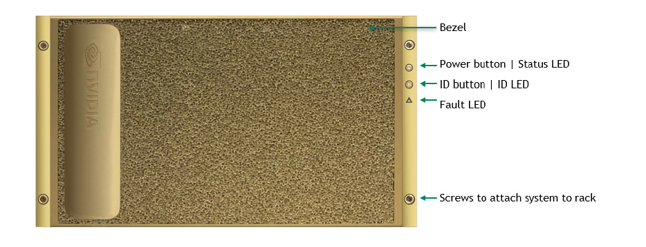
With a Bezel#
Here is an image of the DGX A100 system with a bezel.
Control |
Description |
|---|---|
Power Button |
Press to turn the DGX A100 system On or Off.
|
ID Button |
Press to cause the button blue LED to turn On or blink (configurable through the BMC) as an identifier during servicing. Also causes an LED on the back of the unit to flash as an identifier during servicing. |
Fault LED |
Amber On: System or component faulted |
With the Bezel Removed#
Here is an image of the DGX A100 system with a bezel.
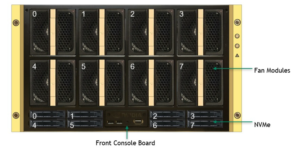
Important
Refer to Turning DGX A100 On and Off for instructions on how to properly turn the system on or off.
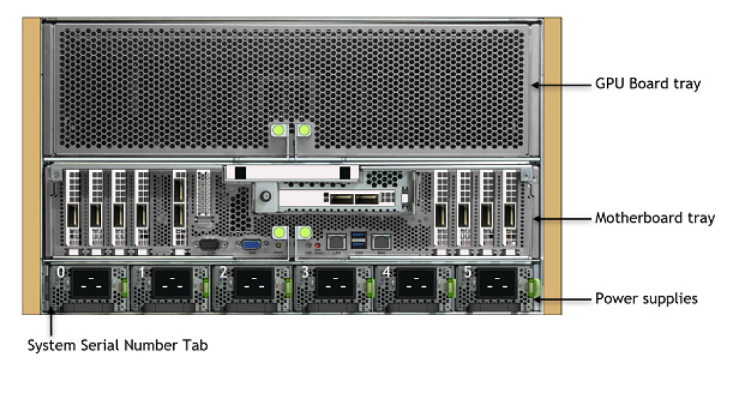
Rear Panel Modules#
Here is an image that shows the real panel modules on DGX A100.
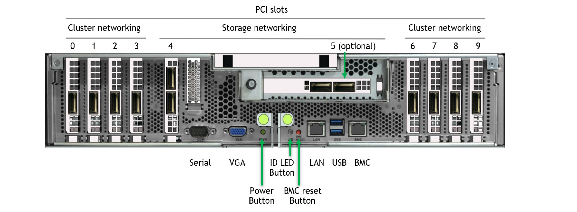
Motherboard Connections and Controls#
Here is an image that shows the motherboard connections and controls in a DGX A100 system.
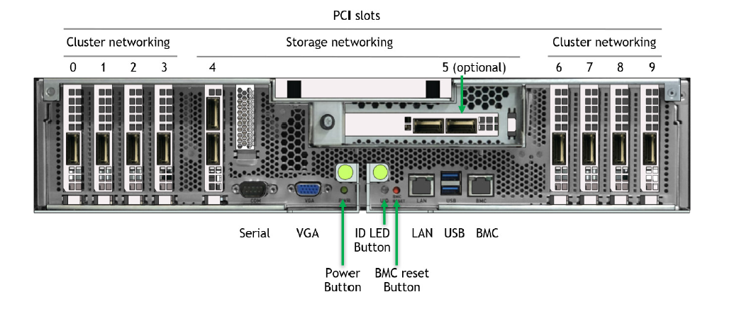
Control |
Description |
|---|---|
Power Button |
Press to turn the system On or Off. |
ID LED Button |
Blinks when ID button is pressed from the front of the unit as an aid in identifying the unit needing servicing. |
BMC Reset button |
Press to manually reset the BMC. |
See Network Connections, Cables, and Adaptors for details on the network connections.
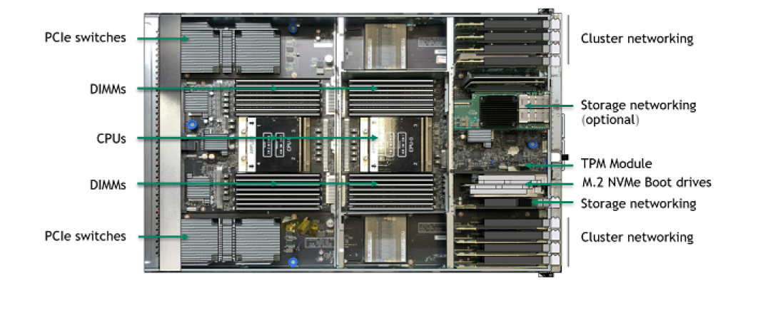
Motherboard Tray Components#
Here is an image that shows the motherboard tray components in DGX A100.
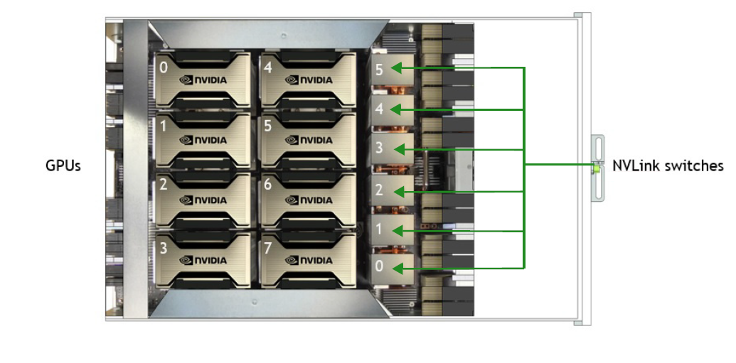
GPU Tray Components#
Here is an image of the GPU tray components in a DGX A100 system.
Network Connections, Cables, and Adaptors#
This section provides information about network connections, cables, and adaptors.
Network Ports#
Here is an image that shows the network ports on a DGX A100 system.
Slot |
PCI Bus |
Port Designation |
RDMA |
|||
|---|---|---|---|---|---|---|
Default |
Optional |
Slot 5 Not Populated |
Slot 5 Populated |
|||
Before DGX OS 6 |
DGX OS 6 and Later |
|||||
0 |
4b:00.0 |
ib2 |
ibp75s0 |
enp75s0 |
mlx5_2 |
mlx5_2 |
1 |
54:00.0 |
ib3 |
ibp84s0 |
enp84s0 |
mlx5_3 |
mlx5_3 |
2 |
ba:00.0 |
ib6 |
ibp186s0 |
enp186s0 |
mlx5_6 |
mlx5_8 |
3 |
cc:00.0 [1] ca:00.0 [2] |
ib7 |
ibp204s0a [3] ibp202s0b [4] |
enp204s0a [5] enp202s0b [6] |
mlx5_7 |
mlx5_9 |
4 port 0 (top) |
e1:00.0 |
enp225s0f0 |
(see note) |
mlx5_8 |
mlx5_10 |
|
4 port 1 (bottom) |
e1:00.1 |
enp225s0f1 |
(see note) |
mlx5_9 |
mlx5_11 |
|
5 port 0 (left) |
61:00.0 |
enp97s0f0 |
(see note) |
mlx5_4 |
||
5 port 1 (right) |
61:00.1 |
enp97s0f1 |
(see note) |
mlx5_5 |
||
6 |
0c:00.0 |
ib0 |
ibp12s0 |
enp12s0 |
mlx5_0 |
mlx5_0 |
7 |
12:00.0 |
ib1 |
ibp18s0 |
enp18s0 |
mlx5_1 |
mlx5_1 |
8 |
8d:00.1 |
ib4 |
ibp141s0 |
enp141s0 |
mlx5_4 |
mlx5_6 |
9 |
94:00.0 |
ib5 |
ibp148s0 |
enp148s0 |
mlx5_5 |
mlx5_7 |
LAN |
e2:00.0 |
enp226s0 |
N/A |
|||
Note
The enp37s0f3u1u3c2 interface or bmc_redfish0 is recognized by the OS and may be listed in response to such commands as ifconfig or ip addr. This interface is reserved for future support of BMC communication using Redfish APIs and is not available for configuration.
Note
The Optional column lists the port designations after reconfiguring the default InfiniBand ports to Ethernet. For DGX A100 systems configured with NVIDIA ConnectX-7 network cards, only the InfiniBand port designations are supported.
When switching from the default Ethernet to InfiniBand, the InfiniBand port designations will vary depending on changes made to the other ports.
BMC Port LEDs#
The BCM RJ-45 port has two LEDs.
The LED on the left indicates the speed. Solid green indicates the speed is 100M. Solid amber indicates the speed is 1G.
The LED on the right is green and flashes to indicate activity.
Supported Network Cables and Adaptors#
The DGX A100 system is not shipped with network cables or adaptors. You will need to purchase supported cables or adaptors for your network.
The ConnectX-6 or ConnectX-7 firmware determines which cables and adaptors are supported. For a list of cables and adaptors compatible with the NVIDIA ConnectX cards installed in the DGX A100 system,
Visit the Mellanox Firmware Release page.
From the left navigation menu, select the ConnectX model and corresponding firmware included in the DGX A100.
Select Firmware Compatible Products.
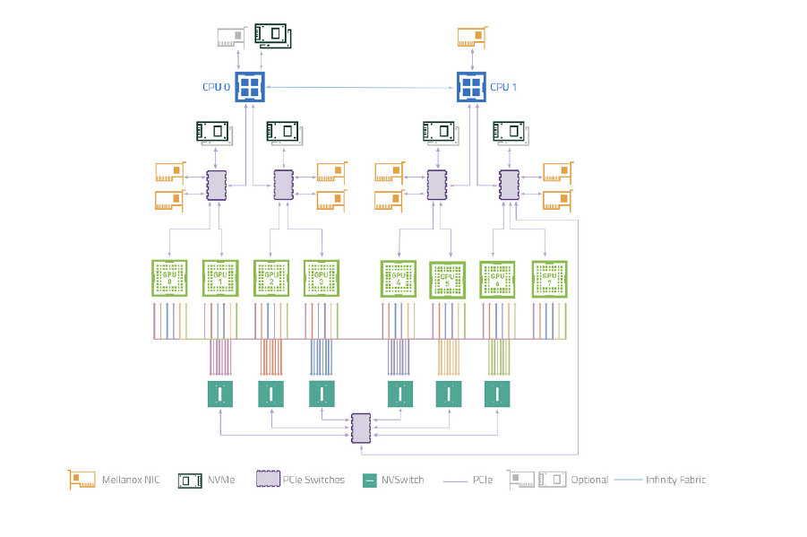
DGX A100 System Topology#
Here is an image of the DGX A100 system topology.
DGX OS Software#
The DGX A100 system comes pre-installed with a DGX software stack incorporating the following components:
An Ubuntu server distribution with supporting packages.
The following system management and monitoring software:
NVIDIA System Management (NVSM)
Provides active health monitoring and system alerts for NVIDIA DGX nodes in a data center. It also provides simple commands for checking the health of the DGX A100 system from the command line.
Data Center GPU Management (DCGM)
This software enables node-wide administration of GPUs and can be used for cluster and data-center level management.
DGX A100 system support packages.
The NVIDIA GPU driver
Docker Engine
NVIDIA Container Toolkit
Mellanox OpenFabrics Enterprise Distribution for Linux (MOFED)
Mellanox Software Tools (MST)
cachefilesd (daemon for managing cache data storage)
Additional Documentation#
This section provides links to additional documentation.
-
The new Multi-Instance GPU (MIG) feature allows the NVIDIA A100 GPU to be securely partitioned into up to seven separate GPU Instances for CUDA applications.
NGC Container Registry for DGX
How to access the NGC container registry for using containerized deep learning GPU- accelerated applications on your DGX A100 system.
-
Contains instructions for using the NVIDIA System Management software.
-
Contains instructions for using the Data Center GPU Manager software.
Customer Support#
Contact NVIDIA Enterprise Support for assistance in reporting, troubleshooting, or diagnosing problems with your DGX A100 system. Also contact NVIDIA Enterprise Support for assistance in moving the DGX A100 system.
For contracted Enterprise Support questions, you can send an email to enterprisesupport@nvidia.com.
For additional details about how to obtain support, go to NVIDIA Enterprise Support.
Our support team can help collect appropriate information about your issue and involve internal resources as needed.