DOCA Firefly Service
NVIDIA DOCA Firefly Service Guide
This document provides instructions on how to use the DOCA Firefly Service container on top of NVIDIA® BlueField® DPU.
DOCA Firefly Service provides precision time protocol (PTP) based time syncing services to the BlueField DPU.
PTP is a protocol used to synchronize clocks in a network. When used in conjunction with hardware support, PTP is capable of sub-microsecond accuracy, which is far better than is what is normally obtainable with network time protocol (NTP). PTP support is divided between the kernel and user space. The ptp4l program implements the PTP boundary clock and ordinary clock. With hardware time stamping, it is used to synchronize the PTP hardware clock to the master clock.
Some of the features provided by Firefly require specific hardware BlueField DPU capabilities:
- PPS – requires special BlueField DPUs with PPS capabilities
- SyncE – requires special BlueField DPUs with SyncE capabilities
- PTP – supported by all BlueField DPUs
Note that failure to run PPS or SyncE due to missing hardware support is noted in the container output, but the container will continue to run the timing services it can provide on the provided hardware, such as PTP.
2.1. Firmware Version
Your firmware version must be 24.33.1048 or higher.
2.2. BlueField BSP Version
The supported BlueField image versions are 3.9.0 and higher.
2.3. Embedded Mode
2.3.1. Configuring Firmware Settings on DPU for Embedded Mode
- Set the DPU to embedded mode (default mode):
sudo mlxconfig -y -d 03:00.0 s INTERNAL_CPU_MODEL=1
- Enable the real time clock (RTC):
sudo mlxconfig -d 03:00.0 set REAL_TIME_CLOCK_ENABLE=1
-
Power cycle the DPU to apply the configuration.
-
You may check the DPU mode using the following command:
            sudo mlxconfig -d 03:00.0 q | grep INTERNAL_CPU_MODEL
# Example output
         INTERNAL_CPU_MODEL                  EMBEDDED_CPU(1)
2.3.2. Ensuring OVS Hardware Offload
DOCA Firefly requires that hardware offload is activated in Open vSwitch (OVS). This is enabled by default as part of the BFB image installed on the DPU. To verify the hardware offload configuration in OVS:
            sudo ovs-vsctl get Open_vSwitch . other_config | grep hw-offload
# Example output
         {hw-offload="true"}
If inactive:
- Activate hardware offloading by running:
sudo ovs-vsctl set Open_vSwitch . other_config:hw-offload=true;
- Restart the OVS service:
sudo /etc/init.d/openvswitch-switch restart
- Power cycle the DPU to apply the configuration.
2.3.3. Helper Scripts
Firefly's deployment contains a script to help with the configuration steps required for the network interface in embedded mode:
- scripts/doca_firefly/<firefly-version>/prepare_for_embedded_mode.sh
- scripts/doca_firefly/<firefly-version>/set_new_sf.sh
The latest DOCA Firefly version is 1.2.0.
Both scripts are included as part of DOCA's container resource which can be downloaded according to the instructions in the NVIDIA DOCA Container Deployment Guide. For more information about the structure of the DOCA container resource, refer to section "Structure of NGC Resource" in the guide.
2.3.3.1. prepare_for_embedded_mode.sh
This script automates all the steps mentioned in section Setting Up Network Interfaces for Embedded Mode and configures a freshly installed BFB image to the settings required by DOCA Firefly. Notes:
- The script deletes all previous OVS settings and creates a single OVS bridge that matches the definitions below
- The script should only be run once when connecting to the DPU for the first time or after a power cycle
- The only manual step required after using this script is configuring the IP address for the created network interface (step 5 in section Setting Up Network Interfaces for Embedded Mode)
Script arguments:
- SF number (checks if already exists)
Examples:
-
Prepare OVS settings using an SF indexed 4:
            chmod +x ./*.sh
./prepare_for_embedded_mode.sh 4
The script makes use of set_new_sf.sh as a helper script.
2.3.3.2. set_new_sf.sh
Creates a new trusted SF and marks it as "trusted". Script arguments:
- PCIe address
- SF number (checks if already exists)
- MAC address (if absent, a random address is generated)
Examples:
- Create SF with number "4" over port 0 of the DPU:
./set_new_sf.sh 0000:03:00.0 4
- Create SF with number "5" over port 0 of the DPU and a specific MAC address:
./set_new_sf.sh 0000:03:00.0 5 aa:bb:cc:dd:ee:ff
- Create SF with number "4" over port 1 of the DPU:
./set_new_sf.sh 0000:03:00.1 4
The first two examples should work out of the box for a BlueField-2 device and create SF4 and SF5 respectively.
2.3.4. Setting Up Network Interfaces for Embedded Mode
- Create a trusted SF to be used by the service according to the Scalable Function Setup Guide.
Note:
The following instructions assume that the SF has been created using index 4.
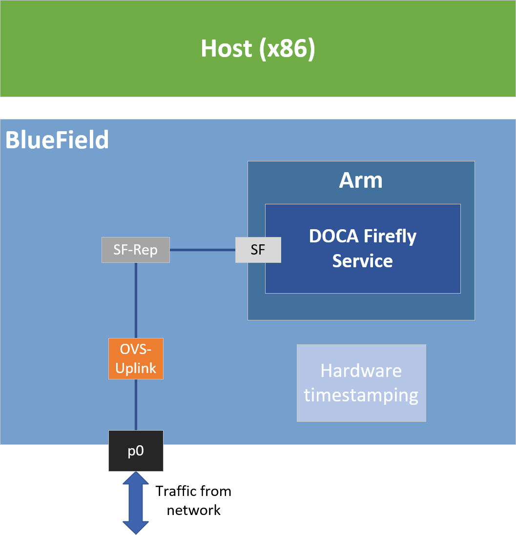
- Create the required OVS setting as is shown in the architecture diagram:
            $ sudo ovs-vsctl add-br uplink
$ sudo ovs-vsctl add-port uplink p0
$ sudo ovs-vsctl add-port uplink en3f0pf0sf4
# This port is needed to ensure we have traffic host<->network as well
$ sudo ovs-vsctl add-port uplink pf0hpf
- Verify the OVS settings:
            sudo ovs-vsctl show
    Bridge uplink
        Port pf0hpf
            Interface pf0hpf
        Port en3f0pf0sf4
            Interface en3f0pf0sf4
        Port p0
            Interface p0
        Port uplink
            Interface uplink
                type: internal
- Enable TX timestamping on the SF interface (not the representor):
            # tx port timestamp offloading
sudo ethtool --set-priv-flags enp3s0f0s4 tx_port_ts on
- Enable the interface and set an IP address for it:
            # configure ip for the interface:
sudo ifconfig enp3s0f0s4 <ip-addr> up
- Configure OVS to support TX timestamping over this SF and multicast traffic in general:
            # Multicast-related definitions
$ sudo ovs-vsctl set Bridge uplink mcast_snooping_enable=true
$ sudo ovs-vsctl set Bridge uplink other_config:mcast-snooping-disable-flood-unregistered=true
$ sudo ovs-vsctl set Port p0 other_config:mcast-snooping-flood=true
$ sudo ovs-vsctl set Port p0 other_config:mcast-snooping-flood-reports=true
# PTP-related definitions
$ sudo ovs-ofctl add-flow uplink in_port=en3f0pf0sf4,udp,tp_src=319,actions=output:p0
$ sudo ovs-ofctl add-flow uplink in_port=p0,udp,tp_src=319,actions=output:en3f0pf0sf4
$ sudo ovs-ofctl add-flow uplink in_port=en3f0pf0sf4,udp,tp_src=320,actions=output:p0
$ sudo ovs-ofctl add-flow uplink in_port=p0,udp,tp_src=320,actions=output:en3f0pf0sf4
Note:If your OVS bridge uses a name other than
uplink, make sure that the used name is reflected in theovs-vsctl set Bridgecommand:$ sudo ovs-vsctl set Bridge <bridge-name> mcast_snooping_enable=true
2.4. Separated Mode
2.4.1. Configuring Firmware Settings on DPU for Separated Mode
- Set the DPU mode to "Separated":
sudo mlxconfig -y -d 03:00.0 s INTERNAL_CPU_MODEL=0
- Enable RTC:
sudo mlxconfig -d 03:00.0 set REAL_TIME_CLOCK_ENABLE=1
- Power cycle the DPU to apply the configuration.
- You may check the DPU mode using the following command:
            sudo mlxconfig -d 03:00.0 q | grep INTERNAL_CPU_MODEL
# Example output
         INTERNAL_CPU_MODEL                  SEPARATED_HOST(0)
2.4.2. Setting Up Network Interfaces for Separated Mode
- Make sure that that
p0is not connected to an OVS bridge:sudo ovs-vsctl show
- Enable TX timestamping on the
p0interface:# TX port timestamp offloading (assuming PTP interface is p0) sudo ethtool --set-priv-flags p0 tx_port_ts on
- Enable the interface and set an IP address for it:
            # Configure IP for the interface
sudo ifconfig p0 <ip-addr> up
2.5. Host-based Deployment
Host-based deployment requires the same configuration described under Separated Mode.
3.1. DPU Deployment
For information about the deployment of DOCA containers on top of the BlueField DPU, refer to NVIDIA DOCA Container Deployment Guide. Service-specific configuration steps and deployment instructions can be found under the service's container page.
DOCA Firefly can also be deployed on DPUs not connected to the Internet. For instructions, refer to the relevant section in the NVIDIA DOCA Container Deployment Guide.
3.2. Host Deployment
DOCA Firefly has a version adapted for host-based deployments. For more information about the deployment of DOCA containers on top of a host, refer to the NVIDIA DOCA Container Deployment Guide. The following is the docker command for deploying DOCA Firefly on the host:
sudo docker run --privileged --net=host -v /var/log/doca/firefly:/var/log/firefly -e PTP_INTERFACE='eth2' -it nvcr.io/nvidia/doca/doca_firefly:1.2.0-doca2.2.0-host /entrypoint.sh
- Additional YAML configs may be passed as environment variables as additional
-ekey-value pairs as done withPTP_INTERFACEabove - The exact container tag should be the desired tag as chosen on DOCA Firefly's NGC page
Both PTP programs included as part of the linuxptp package, ptp4l and phc2sys, have configuration files that allow customizing various PTP-related settings.
4.1. Built-in Config File
Each profile has its own base PTP configuration file for ptp4l. For example, the Media profile PTP configuration file is ptp4l-media.conf.
The built-in PTP configuration files can be found under PTP Profile Default Config Files. For ease-of-use, those files are provided as part of DOCA's container resource as downloaded from NGC and are placed under Firefly's configs directory (scripts/doca_firefly/
When using a built-in configuration file, Firefly uses the files as stored within the container itself in the /etc/linuxptp directory. The configuration files included in the NGC resource are only provided for ease of access. Modifying them does not impact the configuration used in practice by the container. Instead, updates to the configuration should be done as described in the following sections.
4.2. Custom Config File
Instead of using a profile's base config file, users can create a file of their own, for either ptp4l or phc2sys.
To set a custom config file, users should locate their config file in the directory /etc/firefly and set the config file name in DOCA Firefly's YAML file.
For example, to set a custom linuxptp config file, the user can set the parameter PTP_CONFIG_FILE in the YAML file:
            - name: PTP_CONFIG_FILE
  value: my_custom_ptp.conf
In this example, my_custom_ptp.conf should be placed at /etc/firefly/my_custom_ptp.conf.
4.3. Overriding Specific Config File Parameters
Instead of replacing the entire config file, users may opt to override specific parameters. This can be done using the following variable syntax in the YAML file: CONF_<TYPE>_<SECTION>_<PARAMETER_NAME>.
- TYPE – either
PTPorphc2sys - SECTION – the section in the config file that the parameter should be placed in
Note:
If the specified section does not already exist in the config file, a new section is created unless it refers to a PTP network interface that has not been included in the
PTP_INTERFACEYAML field. - PARAMETER_NAME – the config parameter name as should be placed in the config file
Note:
If the parameter name already exists in the config file, then the value is changed according to the value provided in the
.yamlfile. If the parameter name does not already exist in the config file, then it is added.
For example, the following variable in the YAML file definition changes the value of the parameter priority1 under section global in the PTP config file to 64.
            - name: CONF_PTP_global_priority1
  value: "64"
4.4. Ensuring and Debugging Correctness of Config Files
The previous sections describe 2 layers for the configuration file definitions:
- Basic configuration file – either a built-in config file or a custom config file
- Adding/overriding values to/from the YAML file
In practice, there are slightly more layers in place, and the precedence is as follows (presented in increasing order):
- Default configuration values of the PTP program (ptp4l for instance) – holds values of all available configuration options
- Your chosen configuration file – contains a subset of options
- Definitions from the YAML file – narrower subset
- Firefly mandatory values
When combining the supplied configuration file with the definitions from the YAML file, Firefly goes over those definitions and checks them against a predefined set of configuration options:
- Warning only – warns if a certain value leads to known issues in a supported deployment scenario
- Override – container-internal definitions that should not be set by the user and will be overridden by Firefly
Suitable log messages are provided in either case:
            # Example for a warning
2023-01-31 11:55:13 - Firefly - Config - INFO    - Missing explicit definition "fault_reset_interval", verifying default value instead: "4"
2023-01-31 11:55:13 - Firefly - Config - WARNING - Value "4" for definition "fault_reset_interval" will be invalid in Embedded Mode, expected a value lesser or equal to "1"
2023-01-31 11:55:13 - Firefly - Config - WARNING - Continuing with invalid value
# Example for an override
2023-01-31 11:21:00 - Firefly - Config - WARNING - Invalid value "/var/run/ptp4l2" for definition "uds_address", expected "/var/run/ptp4l"
2023-01-31 11:21:00 - Firefly - Config - INFO    - Setting definition "uds_address" value to the following: "/var/run/ptp4l"
At the end of this process, an updated configuration file is generated by Firefly to be used later by the various time providers (as mentioned below). To avoid accidental modification of a user-supplied configuration file or permission issues, the finalized file is generated within the container under the /tmp directory.
For instance, if using a custom configuration file named my_custom_ptp.conf under the /etc/firefly directory on the DPU, the updated file will reside within the container at the following path: /tmp/my_custom_ptp.conf.
For troubleshooting possible issues with the configuration file, users can perform one of the following operations:
- Connect to the container directly as is explained in the "debugging finalized configuration file" bullet under Troubleshooting.
- Map the container's
/tmpdirectory to the DPU using the built-in support in the YAML file:- Before the change:
            # Uncomment when debugging the finalized configuration files used - Part #1
    #- name: debug-firefly-volume
    #  hostPath:
    #    path: /tmp/firefly
    #    type: DirectoryOrCreate
  containers:
    ...
      volumeMounts:
      - name: logs-firefly-volume
        mountPath: /var/log/firefly
      - name: conf-firefly-volume
        mountPath: /etc/firefly
      # Uncomment when debugging the finalized configuration files used - Part #2
      #- name: debug-firefly-volume
      #  mountPath: /tmp
- After the change:
            # Uncomment when debugging the finalized configuration files used - Part #1
    - name: debug-firefly-volume
      hostPath:
        path: /tmp/firefly
        type: DirectoryOrCreate
  containers:
    ...
      volumeMounts:
      - name: logs-firefly-volume
        mountPath: /var/log/firefly
      - name: conf-firefly-volume
        mountPath: /etc/firefly
      # Uncomment when debugging the finalized configuration files used - Part #2
      - name: debug-firefly-volume
        mountPath: /tmp
- Before the change:
5.1. Providers
DOCA Firefly Service uses the following third-party providers to provide time syncing services:
- Linuxptp
PTP– PTP service, provided by the PTP4L programPHC2SYS– OS time calibration, provided by the PHC2SYS program
- Testptp
PPS– PPS settings service
Each of the providers can be enabled, disabled or set to use the setting defined by the configuration profile:
- YAML setting –
<provider-name>_STATE - Supported values –
enable,disable,defined_by_profile
For the default profile settings per provider, refer to the table under Profiles.
The following is an example YAML setting for specifically disabling the phc2sys provider:
            - name: PHC2SYS_STATE
  value: "disable"
5.2. Profiles
DOCA Firefly Service includes profiles which represent common use cases for the Firefly service that provide a different default configuration per profile:
(a) Client-only is only relevant to a single PTP interface. If more than one PTP interface is provided in the YAML file, both modes are enabled.
5.3. Outputs
5.3.1. Container Output
While running, the full output of the DOCA Firefly Service container can be viewed using the following command:
sudo crictl logs <CONTAINER-ID>
Where CONTANIER-ID can be retrieved using the following command:
sudo crictl ps
For example, in the following output, the container ID is 8f368b98d025b.
            $ sudo crictl ps
CONTAINER           IMAGE               CREATED             STATE               NAME                ATTEMPT             POD ID              POD
8f368b98d025b       289809f312b4c       2 seconds ago       Running             doca-firefly        0                   5af59511b4be4       doca-firefly-some-computer-name
The output of the container depends on the services supported by the hardware and enabled via configuration and the profile selected. However, note that any of the configurations runs PTP, so when DOCA FireFly is running successfully expect to see the line Running ptp4l.
The following is an example of the expected container output when running the default profile on a DPU that supports PPS:
            2023-07-10 11:44:17 - Firefly - Init   - INFO    - Starting DOCA Firefly - Version 1.2.0
2023-07-10 11:44:17 - Firefly - Init   - INFO    - Selected features:
2023-07-10 11:44:17 - Firefly - Init   - INFO    - [+] PTP     - Enabled - ptp4l will be used
2023-07-10 11:44:17 - Firefly - Init   - INFO    - [+] PHC2SYS - Enabled - phc2sys will be used
2023-07-10 11:44:17 - Firefly - Init   - INFO    - [+] PPS     - Enabled - testptp will be used (if supported by hardware)
2023-07-10 11:44:17 - Firefly - Init   - INFO    - Going to analyze the configuration files
2023-07-10 11:44:17 - Firefly - Init   - INFO    - Requested the following PTP interface: p0
2023-07-10 11:44:17 - Firefly
2023-07-10 11:44:17 - Firefly - Init   - INFO    - Starting PPS configuration
2023-07-10 11:44:17 - Firefly - Init   - INFO    - [+] PPS is supported by hardware
2023-07-10 11:44:17 - Firefly - Init   - INFO    - set pin function okay
2023-07-10 11:44:17 - Firefly - Init   - INFO    - [+] PPS in - Activated
2023-07-10 11:44:17 - Firefly - Init   - INFO    - set pin function okay
2023-07-10 11:44:17 - Firefly - Init   - INFO    - [+] PPS out - Activated
2023-07-10 11:44:17 - Firefly - Init   - INFO    - name mlx5_pps0 index 0 func 1 chan 0
2023-07-10 11:44:17 - Firefly - Init   - INFO    - name mlx5_pps1 index 1 func 2 chan 0
2023-07-10 11:44:17 - Firefly - Init   - INFO    - periodic output request okay
2023-07-10 11:44:17 - Firefly
2023-07-10 11:44:17 - Firefly - Init   - INFO    - Running ptp4l
2023-07-10 11:44:17 - Firefly - Init   - INFO    - Running Firefly PTP Monitor
2023-07-10 11:44:17 - Firefly - Init   - INFO    - Running phc2sys
The following is an example of the expected container output when running the default profile on a DPU that does not support PPS:
            2023-07-10 11:44:17 - Firefly - Init   - INFO    - Starting DOCA Firefly - Version 1.2.0
2023-07-10 11:44:17 - Firefly - Init   - INFO    - Selected features:
2023-07-10 11:44:17 - Firefly - Init   - INFO    - [+] PTP     - Enabled - ptp4l will be used
2023-07-10 11:44:17 - Firefly - Init   - INFO    - [+] PHC2SYS - Enabled - phc2sys will be used
2023-07-10 11:44:17 - Firefly - Init   - INFO    - [+] PPS     - Enabled - testptp will be used (if supported by hardware)
2023-07-10 11:44:17 - Firefly - Init   - INFO    - Going to analyze the configuration files
2023-07-10 11:44:17 - Firefly - Init   - INFO    - Requested the following PTP interface: p0
2023-07-10 11:44:17 - Firefly
2023-07-10 11:44:17 - Firefly - Init   - INFO    - Starting PPS configuration
2023-07-10 11:44:17 - Firefly - Init   - INFO    - [-] PPS capability is missing, seems that the card doesn't support PPS2023-07-10 11:44:17 - Firefly - Init   - INFO    - capabilities:
2023-07-10 11:44:17 - Firefly - Init   - INFO    -   100000000 maximum frequency adjustment (ppb)
2023-07-10 11:44:17 - Firefly - Init   - INFO    -   0 programmable alarms
2023-07-10 11:44:17 - Firefly - Init   - INFO    -   0 external time stamp channels
2023-07-10 11:44:17 - Firefly - Init   - INFO    -   0 programmable periodic signals
2023-07-10 11:44:17 - Firefly - Init   - INFO    -   0 pulse per second
2023-07-10 11:44:17 - Firefly - Init   - INFO    -   0 programmable pins
2023-07-10 11:44:17 - Firefly - Init   - INFO    -   0 cross timestamping
2023-07-10 11:44:17 - Firefly
2023-07-10 11:44:17 - Firefly - Init   - INFO    - Running ptp4l
2023-07-10 11:44:17 - Firefly - Init   - INFO    - Running Firefly PTP Monitor
2023-07-10 11:44:17 - Firefly - Init   - INFO    - Running phc2sys
Firefly Output
On top of the container's log, Firefly defines an additional, non-volatile log that can be found in /var/log/doca/firefly/firefly.log.
This file contains the same output described under Container Output, and is useful for debugging deployment errors should the container stop its execution.
To avoid disk space issues, the /var/log/doca/firefly/firefly.log file only contains the log from Firefly's initialization, and not the logs of the rest of the modules (ptp4l, phc2sys, etc.) or that of the PTP monitor. The latter is still included in the container log and can be inspected using the command sudo crictl logs <CONTAINER-ID>.
5.3.3. ptp4l Output
The ptp4l output can be found in the file /var/log/doca/firefly/ptp4l.log.
Example output:
            ptp4l[192710.691]: rms 1 max 1 freq -114506 +/- 0 delay -15 +/- 0
ptp4l[192712.692]: rms 6 max 9 freq -114501 +/- 3 delay -15 +/- 0
ptp4l[192714.692]: rms 7 max 9 freq -114511 +/- 3 delay -13 +/- 0
ptp4l[192716.692]: rms 5 max 7 freq -114502 +/- 1 delay -13 +/- 0
ptp4l[192718.693]: rms 4 max 6 freq -114509 +/- 2 delay -13 +/- 0
ptp4l[192720.693]: rms 3 max 3 freq -114506 +/- 2 delay -13 +/- 0
ptp4l[192722.694]: rms 4 max 6 freq -114510 +/- 3 delay -12 +/- 0
ptp4l[192724.694]: rms 5 max 7 freq -114510 +/- 5 delay -12 +/- 1
ptp4l[192726.695]: rms 4 max 5 freq -114508 +/- 3 delay -11 +/- 0
ptp4l[192728.695]: rms 6 max 9 freq -114504 +/- 4 delay -11 +/- 0
5.3.4. phc2sys Output
The phc2sys output can be found in the file /var/log/doca/firefly/phc2sys.log.
Example output:
            phc2sys[1873325.928]: reconfiguring after port state change
phc2sys[1873325.928]: selecting CLOCK_REALTIME for synchronization
phc2sys[1873325.928]: selecting enp3s0f0s4 as the master clock
phc2sys[1873325.928]: CLOCK_REALTIME phc offset      1378 s2 freq -165051 delay    255
phc2sys[1873326.928]: CLOCK_REALTIME phc offset      1378 s2 freq -163673 delay    240
phc2sys[1873327.928]: port 62b785.fffe.0c9369-1 changed state
phc2sys[1873327.929]: CLOCK_REALTIME phc offset        14 s2 freq -164624 delay    255
phc2sys[1873328.936]: CLOCK_REALTIME phc offset        89 s2 freq -164545 delay    240
5.4. Tx Timestamping Support on Embedded Mode
When the DPU is operating in Embedded Mode, additional OVS configuration is needed as mentioned in step 6 under Setting Up Network Interfaces for Embedded Mode. This configuration is associated with the following categories:
- Proper support for incoming/outgoing multicast traffic
- Enabling Tx timestamping
Firefly only gets the packet timestamping for outgoing PTP messages (Tx timestamping) when they are offloaded to the hardware. As such, when working with OVS, you must ensure this traffic flow is properly recognized and offloaded. If the offloading does not take place, Firefly gets stuck in a fault loop while waiting to receive the Tx timestamp events:
            ptp4l[2912.797]: timed out while polling for tx timestamp
ptp4l[2912.797]: increasing tx_timestamp_timeout may correct this issue, but it is likely caused by a driver bug
ptp4l[2912.797]: port 1 (enp3s0f0s4): send sync failed
ptp4l[2923.528]: timed out while polling for tx timestamp
ptp4l[2923.528]: increasing tx_timestamp_timeout may correct this issue, but it is likely caused by a driver bug
ptp4l[2923.528]: port 1 (enp3s0f0s4): send sync failed
The solution to this issue contains several layers:
- Activation of hardware offloading in OVS
- OpenFlow rules that ensure OVS properly recognizes the traffic and offloads it to the hardware
- Modification to the
fault_reset_intervalconfiguration value to ensure timely recovery from the fault induced by the first packet being always treated by software (until the rule is offloaded to hardware)
As such, Firefly requires that the fault_reset_interval value is 1 or less. Proper warnings are raised if an improper value is detected. The value is updated accordingly in the built-in profiles.
When these configurations are in order, Firefly includes a report for a single fault during boot, but recovers from it and continues as usual:
            ptp4l[3715.687]: timed out while polling for tx timestamp
ptp4l[3715.687]: increasing tx_timestamp_timeout may correct this issue, but it is likely caused by a driver bug
ptp4l[3715.687]: port 1 (enp3s0f0s4): send delay request failed
5.4.1. Troubleshooting Tx Timestamp Issues
As explained earlier, there are several layers required to ensure Tx timestamping works as necessary by Firefly. The following is a list of commands to debug the state of each layer:
- Inspecting the OpenFlow rules:
            $ sudo ovs-ofctl dump-flows uplink
cookie=0x0, duration=4075.576s, table=0, n_packets=2437, n_bytes=209582, udp,in_port=en3f0pf0sf4,tp_src=319 actions=output:p0
cookie=0x0, duration=4075.549s, table=0, n_packets=1216, n_bytes=109420, udp,in_port=p0,tp_src=319 actions=output:en3f0pf0sf4
cookie=0x0, duration=4075.521s, table=0, n_packets=13, n_bytes=1242, udp,in_port=en3f0pf0sf4,tp_src=320 actions=output:p0
cookie=0x0, duration=4074.604s, table=0, n_packets=3034, n_bytes=297376, udp,in_port=p0,tp_src=320 actions=output:en3f0pf0sf4
cookie=0x0, duration=4075.856s, table=0, n_packets=184, n_bytes=12901, priority=0 actions=NORMAL
- Inspecting hardware TC rules while DOCA Firefly is deployed (the rules age out after 10 seconds without traffic):
            $ sudo tc -s -d filter show dev en3f0pf0sf4 egress
filter ingress protocol ip pref 4 flower chain 0
filter ingress protocol ip pref 4 flower chain 0 handle 0x1
  eth_type ipv4
  ip_proto udp
  src_port 320
  ip_flags nofrag
  in_hw in_hw_count 1
	action order 1: mirred (Egress Redirect to device p0) stolen
 	index 3 ref 1 bind 1 installed 7 sec used 7 sec
 	Action statistics:
	Sent 0 bytes 0 pkt (dropped 0, overlimits 0 requeues 0)
	backlog 0b 0p requeues 0
	cookie bec8bd6ede4e86341e9045a6edb58ca2
	no_percpu

filter ingress protocol ip pref 4 flower chain 0 handle 0x2
  eth_type ipv4
  ip_proto udp
  src_port 319
  ip_flags nofrag
  in_hw in_hw_count 1
	action order 1: mirred (Egress Redirect to device p0) stolen
 	index 4 ref 1 bind 1 installed 6 sec used 6 sec
 	Action statistics:
	Sent 0 bytes 0 pkt (dropped 0, overlimits 0 requeues 0)
	backlog 0b 0p requeues 0
	cookie c568d97efd400de98608fbbf86ccdf3c
	no_percpu
Note:If no TC rules are present when Firefly is running, this usually indicates that Hardware Offloading is disabled at OVS level, in which case it should be activated as explained under Ensuring OVS Hardware Offload.
5.5. PHC2SYS
Firefly uses the phc2sys utility to synchronize the OS's clock to the accurate time stamps received by ptp4l.
Through the YAML file, one can configure the command-line arguments to be used by the phc2sys program:
            - name: PHC2SYS_ARGS
  value: "-a -r"
Firefly adds the following command-line arguments on top of the user-selected flags:
- Use of chosen configuration file (empty configuration file by default, or user-supplied file if specified in the YAML file)
- Redirection of output to a log file using the
-mcommand line option
phc2sys is only able to accurately sync the clock of the hosting environment (usually the DPU, but may also be the host if deployed there) if other timing services, such as NTP, are disabled. So, for instance, on Ubuntu 22.04, users must ensure that the NTP timing service is disabled by running:
systemctl stop systemd-timesyncd
5.6. PTP Monitoring
Monitoring is still in beta phase. There will be updates to the API in the near future.
PTP monitoring periodically queries for various PTP-related information and prints it to the container's log. The following is a sample output of this tool:
            gmIdentity:                E8:1B:D5:FF:FE:64:E5:03 (e81bd5.fffe.64e503)
portIdentity:              62:B7:85:FF:FE:0C:93:69 (62b785.fffe.0c9369-1)
master_offset (max):       8
master_offset (avg):       5
gmPresent:                 true
ptp_stable:                Recovered
UtcOffset:                 37
timeTraceable:             0
frequencyTraceable:        0
grandmasterPriority1:      128
gmClockClass:              248
gmClockAccuracy:           0xfe
grandmasterPriority2:      127
gmOffsetScaledLogVariance: 0xffff
ptp_time:                  Tue Dec 27 16:24:58 2022
system_time:               Tue Dec 27 16:24:21 2022
error_count:               1
last_err_time:             Tue Dec 27 16:22:56 2022
Among others, this monitoring provides the following information:
- Details about the Grandmaster the DPU is syncing with
- Current PTP timestamp
- Health information such as connection errors during execution and whether they have been recovered from
PTP monitoring is disabled by default and can be activated by replacing the disable value with the IP address for the monitor server to use:
            - name: PTP_MONITOR
  value: "<IP address for the monitoring server>"
Once activated, the information can viewed from the container using the following command:
sudo crictl logs --tail=20 <CONTAINER-ID>
It is recommended to use the following watch command to actively monitor the PTP state:
sudo watch -n 1 crictl logs --tail=20 <CONTAINER-ID>
The monitoring feature makes use of the PMC utility and connects to ptp4l's local read-only UDS server to query the necessary information. This is why the configuration manager prevents users from modifying the uds_ro_address used by ptp4l within the container.
Time Representations
Under most deployment scenarios, the PTP time as shown by the monitor is presented according to the International Atomic Time (TAI) standard, while the system time would most commonly use the Coordinated Universal Time (UTC). Due to the differences between these time representation models, even when the phc2sys module is activated, there would be a small difference between the two monitor values:
            ...
UtcOffset:                 37
...
ptp_time:                  Tue Dec 27 16:24:58 2022
system_time:               Tue Dec 27 16:24:21 2022
This difference (37 seconds in the above example) is intentional and stems from the amount of leap seconds since epoch. This is indicated by the UtcOffset field that is also included in the monitor's report.
5.6.2. Monitor Server
On top of printing the monitoring data to the container's standard output available through the container logs, the monitoring data is also exposed through a gRPC server that clients can subscribe to. This allows a monitoring client on the host to subscribe to monitor events from the service running on top of the DPU, thus providing better visibility.
The following diagram presents the recommended deployment architecture for connecting the monitoring client (on the host) to the monitor server (on the DPU), based on the NVIDIA DOCA gRPC Infrastructure User Guide.
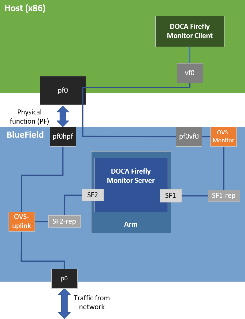
Based on the above, when activating the monitor feature, the user must provide the IP address to be used by the monitor server:
            - name: PTP_MONITOR
        value: "<IP address for the monitoring server>"
Users can choose to only view the monitoring events through the container logs without connecting to the monitoring server. In this case it is recommended to configure the local host IP address (127.0.0.1) in the YAML file to avoid exposing it to an unwanted network.
5.6.3. Monitor Client
All the required files for the monitor client are available under the service's dedicated installation directory:
- Linux installations –
/opt/mellanox/doca/services/firefly - Windows installation –
C:\Program Files\Mellanox\DOCA\SDK\firefly - Example command line for executing the compiled monitor client from a Linux host:
$ /opt/mellanox/doca/services/firefly/bin/doca_firefly_monitor_client -g <ip-address-for-the-monitoring-server>
- Example command line for executing the python-based monitor client from a Windows host:
- Installing required pip packages:
$ pip3 install grpcio protobuf click
- Running the client:
$ C:\Program Files\Mellanox\DOCA\SDK\firefly\bin\doca_firefly_monitor_client.py <ip-address-for-the-monitoring-server>
- Installing required pip packages:
- Example command line for executing the python-based monitor client from a Linux host:
            $ export PYTHONPATH=${PYTHONPATH}:/opt/mellanox/grpc/python3/lib
$ /opt/mellanox/doca/services/firefly/bin/doca_firefly_monitor_client.py <ip-address-for-the-monitoring-server>
Reference source files and the .proto file used for Firefly's monitor are placed under firefly/src/monitor.
5.7. VLAN Tagging
DOCA Firefly natively supports VLAN tagging enabled network interfaces.
5.7.1. Separated Mode
The name of the VLAN-enabled network interface should be the one passed through the YAML file in the PTP_INTERFACE field.
5.7.2. Embedded Mode
On top of passing on the VLAN-enabled interface through the YAML as listed in the previous section, the user is also required to configure the network routing within the DPU to support the VLAN tagging:
- The following example configures a VLAN tag of 10 to the
enp3s0f0s4interface:$ sudo ip link add link enp3s0f0s4 name enp3s0f0s4.10 type vlan id 10 $ sudo ip link set up enp3s0f0s4.10 $ sudo ifconfig enp3s0f0s4.10 192.168.104.1 up
In this example,
enp3s0f0s4.10is the interface to be passed to DOCA Firefly. - Additional commands to route the traffic within the DPU:
            $ sudo ovs-ofctl add-flow uplink in_port=en3f0pf0sf4,dl_vlan=10,actions=output:p0
$ sudo ovs-ofctl add-flow uplink in_port=p0,dl_vlan=10,actions=output:en3f0pf0sf4
5.8. Multiple Interfaces
DOCA Firefly can support multiple network interfaces through the following YAML file syntax:
            - name: PTP_INTERFACE
  value: "<space (' ') separated list of interface names>"
For example:
            - name: PTP_INTERFACE
  value: "p0 p1"
For general troubleshooting purposes, refer to NVIDIA DOCA Troubleshooting Guide.
For container-related troubleshooting, refer to the "Troubleshooting" section in the NVIDIA DOCA Container Deployment Guide. The following are additional troubleshooting tips for DOCA Firefly Service:
- If no pod is created, verify that your YAML is written correctly (see NVIDIA DOCA Troubleshooting Guide) and check the output of the following command:
sudo journalctl -u kubelet
- If the pod's STATE fails to be marked as
Ready(check usingcirctl pods), check if the container has run and exited:- Check the container's state:
sudo crictl ps -a
- If the container did exit, use the container's ID to check the log output by running:
sudo crictl logs <container-id>
- Should the container fail (i.e., state of
Exited) it is recommended to examine Firefly's main log at/var/log/doca/firefly/firefly.log.
- Check the container's state:
- If the error
custom config file not foundappears in the container log, check the custom file name written in the YAML file and make sure that you properly placed the file with that name under the/etc/firefly/directory. - If the error
profile <name> is not supported. Abortingappears in the container log, verify that the profile you selected in the YAML file matches one of the optional profiles as listed in the profiles table. - If the message
PPS capability is missing, seems that the card doesn't support PPSappears in the container log, then the DPU hardware does not support PPS. However, PTP can still run on this hardware and you should see the lineRunning ptp4lin the container log which indicates that PTP is running successfully. - To debug the finalized configuration file used by Firefly, you can connect to the container as follows:
- Open a shell session on the running container using the container ID (which can be queried as mentioned above):
sudo crictl exec -it <container-id> /bin/bash
- Once connected the to container, the finalized configuration file can be found under the
/tmpdirectory using the same filename as the original configuration file.
Note:More information regarding the configuration files can be found under Ensuring and Debugging Correctness of Config Files.
- Open a shell session on the running container using the container ID (which can be queried as mentioned above):
7.1. Media Profile
            #
# This config file contains configurations for media & entertainment alongside
# DOCA Firefly-specific adjustments.
#

[global]
domainNumber            127
priority1               128
priority2               127
use_syslog                1
logging_level             6
tx_timestamp_timeout     30
hybrid_e2e                1
dscp_event               46
dscp_general             46
logAnnounceInterval      -2
announceReceiptTimeout    3
logSyncInterval          -3
logMinDelayReqInterval   -3
delay_mechanism         E2E
network_transport     UDPv4
# Value lesser or equal to 1 is required for Embedded Mode
fault_reset_interval      1
# Required for multiple interfaces support
boundary_clock_jbod       1
7.2. Default Profile
            #
# This config file extends linuxptp default.cfg config file with DOCA
# Firefly-specific adjustments.
#

[global]
# Value lesser or equal to 1 is required for Embedded Mode
fault_reset_interval                 1
# Required for multiple interfaces support
boundary_clock_jbod                  1
Notice
This document is provided for information purposes only and shall not be regarded as a warranty of a certain functionality, condition, or quality of a product. NVIDIA Corporation nor any of its direct or indirect subsidiaries and affiliates (collectively: “NVIDIA”) make no representations or warranties, expressed or implied, as to the accuracy or completeness of the information contained in this document and assume no responsibility for any errors contained herein. NVIDIA shall have no liability for the consequences or use of such information or for any infringement of patents or other rights of third parties that may result from its use. This document is not a commitment to develop, release, or deliver any Material (defined below), code, or functionality.
NVIDIA reserves the right to make corrections, modifications, enhancements, improvements, and any other changes to this document, at any time without notice.
Customer should obtain the latest relevant information before placing orders and should verify that such information is current and complete.
NVIDIA products are sold subject to the NVIDIA standard terms and conditions of sale supplied at the time of order acknowledgement, unless otherwise agreed in an individual sales agreement signed by authorized representatives of NVIDIA and customer (“Terms of Sale”). NVIDIA hereby expressly objects to applying any customer general terms and conditions with regards to the purchase of the NVIDIA product referenced in this document. No contractual obligations are formed either directly or indirectly by this document.
NVIDIA products are not designed, authorized, or warranted to be suitable for use in medical, military, aircraft, space, or life support equipment, nor in applications where failure or malfunction of the NVIDIA product can reasonably be expected to result in personal injury, death, or property or environmental damage. NVIDIA accepts no liability for inclusion and/or use of NVIDIA products in such equipment or applications and therefore such inclusion and/or use is at customer’s own risk.
NVIDIA makes no representation or warranty that products based on this document will be suitable for any specified use. Testing of all parameters of each product is not necessarily performed by NVIDIA. It is customer’s sole responsibility to evaluate and determine the applicability of any information contained in this document, ensure the product is suitable and fit for the application planned by customer, and perform the necessary testing for the application in order to avoid a default of the application or the product. Weaknesses in customer’s product designs may affect the quality and reliability of the NVIDIA product and may result in additional or different conditions and/or requirements beyond those contained in this document. NVIDIA accepts no liability related to any default, damage, costs, or problem which may be based on or attributable to: (i) the use of the NVIDIA product in any manner that is contrary to this document or (ii) customer product designs.
No license, either expressed or implied, is granted under any NVIDIA patent right, copyright, or other NVIDIA intellectual property right under this document. Information published by NVIDIA regarding third-party products or services does not constitute a license from NVIDIA to use such products or services or a warranty or endorsement thereof. Use of such information may require a license from a third party under the patents or other intellectual property rights of the third party, or a license from NVIDIA under the patents or other intellectual property rights of NVIDIA.
Reproduction of information in this document is permissible only if approved in advance by NVIDIA in writing, reproduced without alteration and in full compliance with all applicable export laws and regulations, and accompanied by all associated conditions, limitations, and notices.
THIS DOCUMENT AND ALL NVIDIA DESIGN SPECIFICATIONS, REFERENCE BOARDS, FILES, DRAWINGS, DIAGNOSTICS, LISTS, AND OTHER DOCUMENTS (TOGETHER AND SEPARATELY, “MATERIALS”) ARE BEING PROVIDED “AS IS.” NVIDIA MAKES NO WARRANTIES, EXPRESSED, IMPLIED, STATUTORY, OR OTHERWISE WITH RESPECT TO THE MATERIALS, AND EXPRESSLY DISCLAIMS ALL IMPLIED WARRANTIES OF NONINFRINGEMENT, MERCHANTABILITY, AND FITNESS FOR A PARTICULAR PURPOSE. TO THE EXTENT NOT PROHIBITED BY LAW, IN NO EVENT WILL NVIDIA BE LIABLE FOR ANY DAMAGES, INCLUDING WITHOUT LIMITATION ANY DIRECT, INDIRECT, SPECIAL, INCIDENTAL, PUNITIVE, OR CONSEQUENTIAL DAMAGES, HOWEVER CAUSED AND REGARDLESS OF THE THEORY OF LIABILITY, ARISING OUT OF ANY USE OF THIS DOCUMENT, EVEN IF NVIDIA HAS BEEN ADVISED OF THE POSSIBILITY OF SUCH DAMAGES. Notwithstanding any damages that customer might incur for any reason whatsoever, NVIDIA’s aggregate and cumulative liability towards customer for the products described herein shall be limited in accordance with the Terms of Sale for the product.
Trademarks
NVIDIA, the NVIDIA logo, and Mellanox are trademarks and/or registered trademarks of Mellanox Technologies Ltd. and/or NVIDIA Corporation in the U.S. and in other countries. The registered trademark Linux® is used pursuant to a sublicense from the Linux Foundation, the exclusive licensee of Linus Torvalds, owner of the mark on a world¬wide basis. Other company and product names may be trademarks of the respective companies with which they are associated.
Copyright
© 2023 NVIDIA Corporation & affiliates. All rights reserved.