DOCA DevEmu PCI Generic
This library is supported at the alpha level; backward compatibility is not guaranteed.
This guide provides instructions on building and developing applications that require emulation of a generic PCIe device.
DOCA DevEmu PCI Generic is part of the DOCA Device Emulation subsystem. It provides low-level software APIs that allow creation of a custom PCIe device using the emulation capability of NVIDIA® BlueField®.
For example, it enables emulating an NVMe device by creating a generic emulated device, configuring its capabilities and BAR to be compliant with the NVMe spec, and operating it from the DPU as necessary.
This library follows the architecture of a DOCA Core Context. It is recommended read the following sections beforehand :
Generic device emulation is part of DOCA PCIe device emulation. It is recommended to read the following guides beforehand:
DOCA DevEmu PCI Generic Emulation is supported only on the BlueField target. The BlueField must meet the following requirements:
DOCA version 2.7.0 or greater
BlueField-3 firmware 32.41.1000 or higher
Please refer to the DOCA Backward Compatibility Policy.
Library must be run with root privileges.
Please refer to DOCA DevEmu PCI Environment, for further necessary configurations.
DOCA DevEmu PCI Generic allows the creation of a generic PCI type. The PCI Type is part of the DOCA DevEmu PCI library. It is the component responsible for configuring the capabilities and bar layout of emulated devices.
The PCI Type can be considered as the template for creating emulated devices. Such that the user first configures a type, and then they can use it to create multiple emulated devices that have the same configuration.
For a more concrete example, consider that you would like to emulate an NVMe device, then you would create a type and configure its capabilities and BAR to be compliant with the NVMe spec, after that you can use the same type, to generate multiple NVMe emulated devices.
PCIe Configuration Space
The PCIe configuration space is 256 bytes long and has a header that is 64 bytes long. Each field can be referred to as a register (e.g., device ID).
Every PCIe device is required to implement the PCIe configuration space as defined in the PCIe specification.
The host can then read and/or write to registers in the PCIe configuration space. This allows the PCIe driver and the BIOS to interact with the device and perform the required setup.
It is possible to configure registers in the PCIe configuration space header as shown in the following diagram:
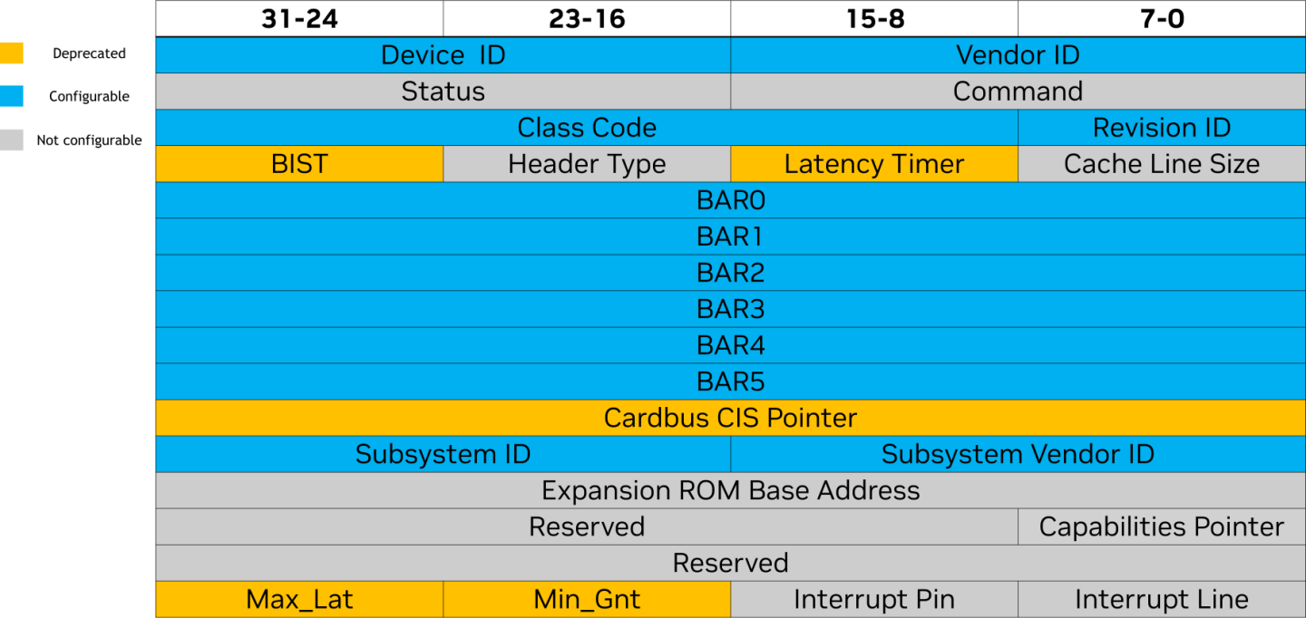
0x0 is the only supported header type (general device).
The following registers are read-only, and they are used to identify the device:
Register Name | Description | Example |
Class Code | Defines the functionality of the device Can be further split into 3 values {class : subclass: prog IF} | 0x020000 Class: 0x02 (Network Controller) Subclass: 0x00 (Ethernet Controller) Prog IF: 0x00 (N/A) |
Revision ID | Unique identifier of the device revision Vendor allocates ID by itself | 0x01 (Rev 01) |
Vendor ID | Unique identifier of the chipset vendor Vendor allocates ID from the PCI-SIG | 0x15b3 Nvidia |
Device ID | Unique identifier of the chipset Vendor allocates ID by itself | 0xa2dc BlueField-3 integrated ConnectX-7 network controller |
Subsystem Vendor ID | Unique identifier of the card vendor Vendor allocates ID from the PCI-SIG | 0x15b3 Nvidia |
Subsystem ID | Unique identifier of the card Vendor allocates ID by itself | 0x0051 |
BAR
While the PCIe configuration space can be used to interact with the PCIe device, it is not enough to implement the functionality that is targeted by the device. Rather, it is only relevant for the PCIe layer.
To enable protocol-specific functionality, the device configures additional memory regions referred to as base address registers (BARs) that can be used by the host to interact with the device. Different from the PCIe configuration space, BARs are defined by the device and interactions with them is device-specific. For example, the PCIe driver interacts with an NVMe device's PCIe configuration space according to the PCIe spec, while the NVMe driver interacts with the BAR regions according to the NVMe spec.
Any read/write requests on the BAR are typically routed to the hardware, but in case of an emulated device, the requests are routed to the software.
The DOCA DevEmu PCI type library provides APIs that allow software to pick the mechanism used for routing the requests to software, while taking into consideration common design patterns utilized in existing devices.
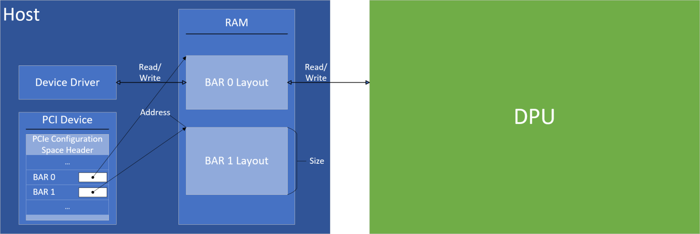
Each PCIe device can have up to 6 BARs with varying properties. During the PCIe bus enumeration process, the PCIe device must be able to advertise information about the layout of each BAR. Based on the advertised information, the BIOS/OS then allocates a memory region for each BAR and assigns the address to the relevant BAR in the PCIe configuration space header. The driver can then use the assigned memory address to perform reads/writes to the BAR.
BAR Layout
The PCIe device must be able to provide information with regards to each BAR's layout.
The layout can be split into 2 types, each with their own properties as detailed in the following subsections.
I/O Mapped
According to the PCIe specification, the following represents the I/O mapped BAR:

Additionally, the BAR register is responsible for advertising the requested size during enumeration.
The size must be a power of 2.
Users can use the following API to set a BAR as I/O mapped:
doca_devemu_pci_type_set_io_bar_conf(struct doca_devemu_pci_type *pci_type, uint8_t id, uint8_t log_sz)
id– the BAR IDlog_sz– the log of the BAR size
Memory Mapped
According to the PCIe specification, the following represents the memory mapped BAR:

Additionally, the BAR register is responsible for advertising the requested size during enumeration.
The size must be a power of 2.
The memory mapped BAR allows a 64-bit address to be assigned. To achieve this, users must specify the bar Memory Type as 64-bit, and then set the next BAR's (BAR ID + 1) size to be 0.
Setting the pre-fetchable bit indicates that reads to the BAR have no side-effects.
Users can use the following API to set a BAR as memory mapped:
doca_devemu_pci_type_set_memory_bar_conf(struct doca_devemu_pci_type *pci_type, uint8_t id, uint8_t log_sz, enum doca_devemu_pci_bar_mem_type memory_type, uint8_t prefetchable)
id– the BAR IDlog_sz– the log of the BAR size. If set to 0, then the size is considered as 0 (instead of 1).memory_type– specifies the memory type of the BAR. If set to 64-bit, then the next BAR must havelog_szset to 0.prefetchable– indicates whether the BAR memory is pre-fetchable or not (a value of 1 or 0 respectively)
BAR Regions
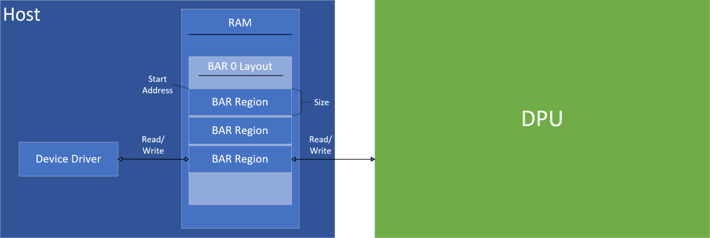
BAR regions refer to memory regions that make up a BAR layout. This is not something that is part of the PCIe specification, rather it is a DOCA concept that allows the user to customize behavior of the BAR when interacted with by the host.
The BAR region defines the behavior when the host performs a read/write to an address within the BAR, such that every address falls in some memory region as defined by the user.
Common Configuration
All BAR regions have these configurations in common:
id– the BAR ID that the region is part ofstart_addr– the start address of the region within the BAR layout relative to the BAR. 0 indicates the start of the BAR layout.size– the size of the BAR region
Currently, there are 4 BAR region types, defining different behavior:
Stateful
DB by offset
DB by data
MSIX table
MSIX PBA
Generic Control Path (Stateful BAR Region)
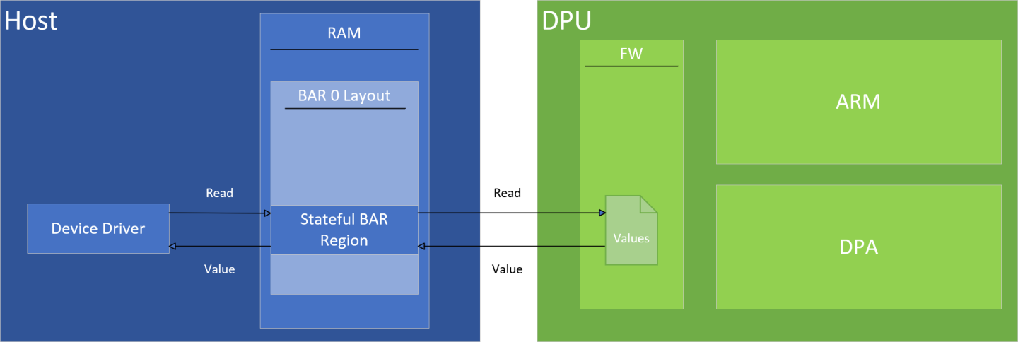
Stateful region can be used as a shared memory, such that the contents are maintained in firmware. A read from the driver returns the latest value, while a write updates the value and triggers an event to software running on the DPU.
This can be useful for communication between the driver and the device, during the control path (e.g., exposing capabilities, initialization).
Some limitations apply, please see Limitations section
Driver Read
A read from the driver returns the latest value written to the region, whether written by the host or by the driver itself.
Driver Write
A write from the driver updates the value at the written address and notifies software running on the Arm that a write has occurred. The notification on the Arm arrives as an asynchronous event (see doca_devemu_pci_dev_event_bar_stateful_region_driver_write).
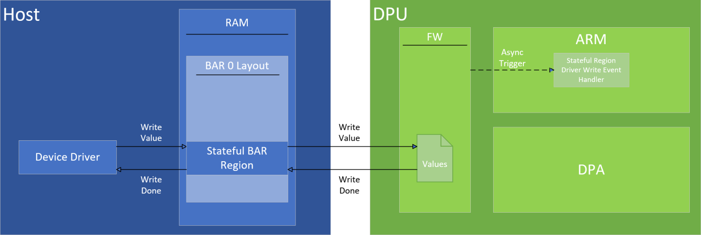
The event that arrives to Arm software is asynchronous such that it may arrive after the driver has completed the write.
DPU Read
The DPU can read the values of the stateful region using doca_devemu_pci_dev_query_bar_stateful_region_values. This returns the latest snapshot of the stateful region values. It can be particularly useful to find what was written by the driver after the "stateful region driver write event" occurs.
DPU Write
The DPU can write the values of the stateful region using doca_devemu_pci_dev_modify_bar_stateful_region_values. This updates the values such that subsequent reads from the driver or the DPU returns these values.
Default Values
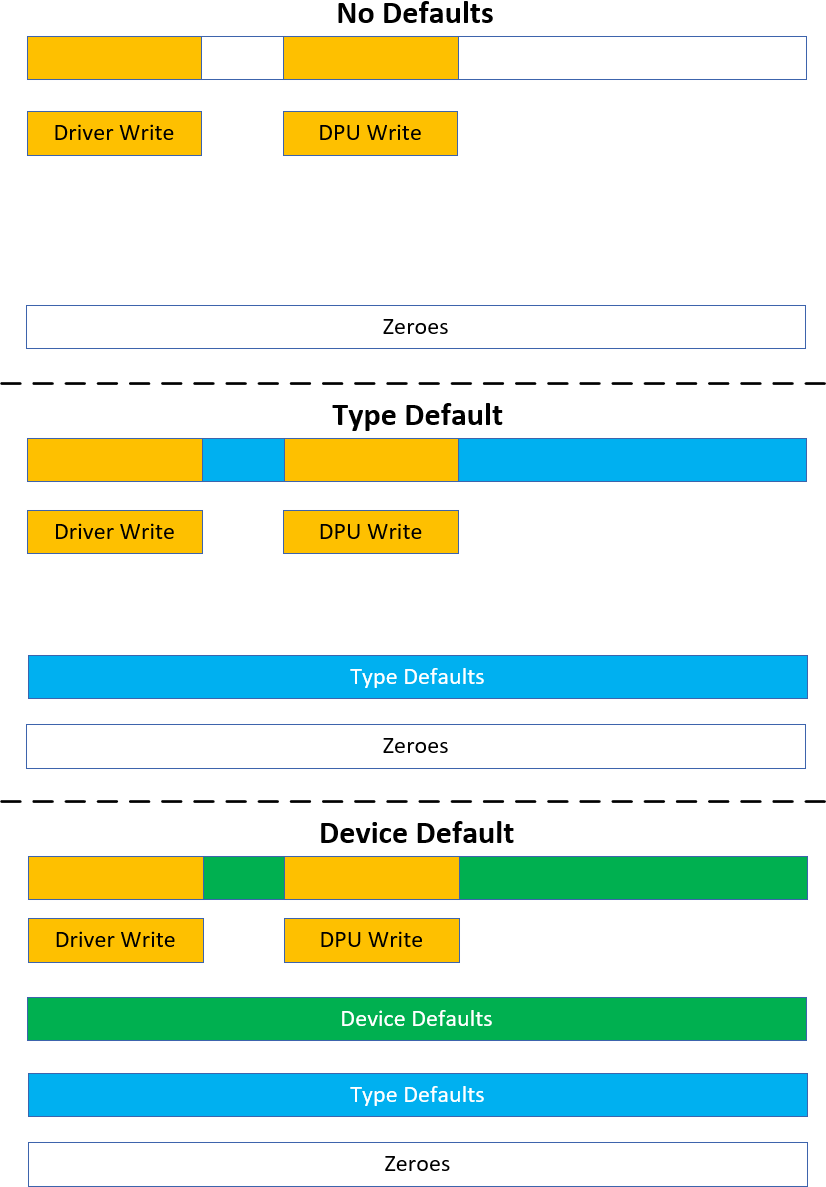
The DPU can set default values to the stateful region. Default values come in 2 layers:
Type default values – these values are set for all devices that have the same type. This can be set only if no device currently exists.
Device default values – these values are set for a specific device and take effect on the next FLR cycle or the next hotplug of the device
A read of the stateful region follows the following hierarchy:
Return the latest value as written by the host or driver (whichever was done last).
Return the device default values.
Return the type default values.
Return 0.
Generic Data Path (DB BAR Region)
Doorbell (DB) regions can be used to implement a consumer-producer queue between the driver and the DPU, such that a write from the driver would trigger an event on the DPU through DPA, allowing it to fetch the written value. This can be useful for communication between the driver and the device, during the data path allowing IO processing.
While DBs are not part of the PCIe specification, it is a widely used mechanism by vendors (e.g., RDMA QP, NVMe SQ, virtio VQ, etc).
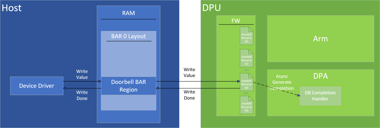
The same DB region can be used to manage multiple DBs, such that each DB can be used to implement a queue.
The DPU software can utilize DB resources individually:
Each DB resource has a unique zero-based index referred to as DB ID
DB resource can be managed (create/destroy/modify/query) individually
Each DB resource has a separate notification mechanism. That is, the notification on DPU is triggered for each DB separately.
Driver Write
The DB usually consists of a numeric value (e.g., uint32_t) representing the consumer/producer index of the queue.
When the driver writes to the DB region, the related DB resource gets updated with the written value, and a notification is sent to the DPU.
When driver writes to the DB BAR region it must adhere to the following:
The size of the write must match the size of the DB value (e.g.,
uint32_t)The offset within the region must be aligned to the DB stride size or the DB size
The flow would look something as the following:
Driver performs a write of the DB value at some offset within the DB BAR region
DPU calculates the DB ID that the write is intended for. Depending on the region type:
DB by offset – DPU calculates the DB ID based on the write offset relative to the DB BAR region
DB by data – DPU parses the written DB value and extracts the DB ID from it
DPU updates the DB resource with the matching DB ID to the value written by the driver
DPU sends a notification to the DPA application, informing it that the value of DB with DB ID has been updated by the driver
Driver Read
The driver should not attempt to read from the DB region. Doing so results in anomalous behavior.
BlueField Write
The BlueField can update the value of each DB resource individually using doca_devemu_pci_db_modify_value. This produces similar side effects as though the driver updated the value using a write to the DB region.
BlueField Read
The BlueField can read the value of each DB resource individually using one of the following methods:
Read the value from the BlueField Arm using
doca_devemu_pci_db_query_valueRead the value from the DPA using
doca_dpa_dev_devemu_pci_db_get_value
The first option is a time consuming operation and is only recommended for the control path. In the data path, it is recommended to use the second option only.
DB by Offset
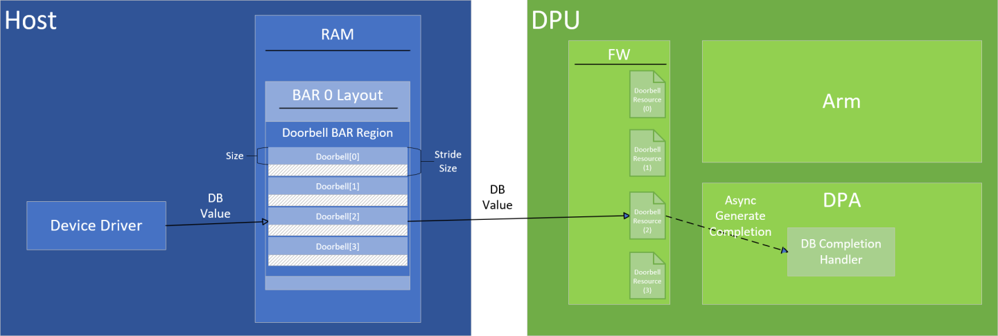
The API doca_devemu_pci_type_set_bar_db_region_by_offset_conf can be used to set up DB by offset region. When the driver writes a DB value using this region, the DPU receives a notification for the relevant DB resource, based on the write offset, such that the DB ID is calculated as follows: db_id=write_offset/db_stride_size.
The area that is part of the stride but not part of the doorbell, should not be used for any read/write operation, doing so will result in undefined anomalous.
DB by Data
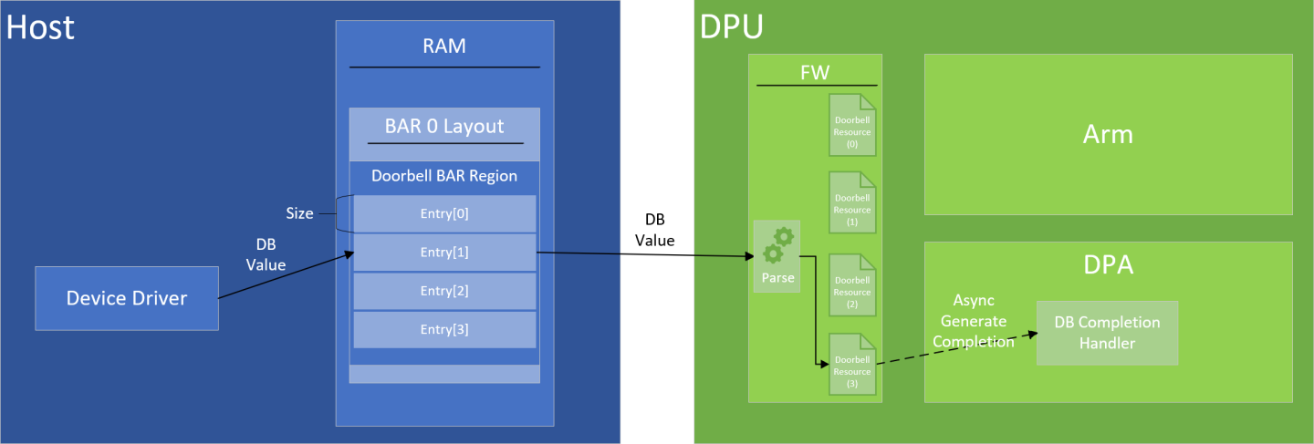
The API doca_devemu_pci_type_set_bar_db_region_by_data_conf can be used to set up DB by data region. When the driver writes a DB value using this region, the DPU receives a notification for the relevant DB resource based on the written DB value, such that there is no relation between the write offset and the DB triggered. This DB region assumes that the DB ID is embedded within the DB value written by the driver. When setting up this region, the user must specify where the Most Significant Byte (MSB) and Least Significant Byte (LSB) of the DB ID are embedded in the DB value.
The DPU follows these steps to extract the DB ID from the DB value:
Driver writes the DB value
BlueField extracts the bytes between MSB and LSB
DPU compares MSB index with LSB index
If MSB index greater than LSB index: The extracted value is interpreted as Little Endian
If LSB index greater than MSB index: The extracted value is interpreted as Big Endian
Example:
DB size is 4 bytes, LSB is 1, and MSB is 3.
Driver writes value
0xCCDDEEFFto DB region at index 0 in Little EndianThe value is written to memory as follows:
[0]=FF [1]=EE [2]=DD [3]=CC
The relevant bytes, are the following:
[1]=EE [2]=DD [3]=CCSince MSB (3) is greater than LSB (1), the value is interpreted as Little Endian:
db_id = 0xCCDDEE
MSI-X Capability (MSI-X BAR Region)
Message signaled interrupts extended (MSI-X) is commonly used by PCIe devices to send interrupts over the PCIe bus to the host driver. DOCA APIs allow users to expose the MSI-X capability as per the PCIe specification, and to later use it to send interrupts to the host driver.
To configure it, users must provide the following:
The number of MSI-X vectors which can be done using
doca_devemu_pci_type_set_num_msixDefine an MSI-X table
Define an MSI-X PBA
MSI-X Table BAR Region
As per the PCIe specification, to expose the MSI-X capability, the device must designate a memory region within its BAR as an MSI-X table region. In DOCA, this can be done using doca_devemu_pci_type_set_bar_msix_table_region_conf.
MSI-X PBA BAR Region
As per the PCIe specification, to expose the MSI-X capability, the device must designate a memory region within its BAR as an MSI-X pending bit array (PBA) region. In DOCA, this can be done using doca_devemu_pci_type_set_bar_msix_pba_region_conf.
Raising MSI-X From DPU
It is possible to raise an MSI-X for each vector individually. This can be done only using the DPA API doca_dpa_dev_devemu_pci_msix_raise.
DMA Memory
Some operations require accessing memory which is set up by the host driver. DOCA's device emulation APIs allow users to access such I/O memory using the DOCA mmap (see DOCA Core Memory Subsystem).
After starting the PCIe device, it is possible to acquire an mmap that references the host memory using doca_devemu_pci_mmap_create. After creating this mmap, it is possible to configure it by providing:
Access permissions
Host memory range
DOCA devices that can access the memory
The mmap can then be used to create buffers that reference memory on the host. The buffers' addresses would not be locally accessible (i.e., CPU cannot dereference the address), instead the addresses would be I/O addresses as defined by the host driver.
The buffers created from the mmap can then be used with other DOCA libraries and accept a doca_buf as an input. This includes:
Function Level Reset
FLR can be handled as described in DOCA DevEmu PCI FLR. Additionally, users must ensure that the following resources are destroyed before stopping the PCIe device:
Doorbells created using
doca_devemu_pci_db_create_on_dpaMSI-X vectors created using
doca_devemu_pci_msix_create_on_dpaMemory maps created using
doca_devemu_pci_mmap_create
Limitations
Based on explanation in "Driver Write", user can assume that DOCA DevEmu PCI Generic supports creating emulated PCI devices with the limitation that when a driver writes to a register, the value is immediately available for subsequent reads from the same register. However, this immediate availability does not ensure that any required internal actions triggered by the write have been completed. It is recommended to rely on specific different register values to confirm completion of the write action. For instance, when implementing a write-to-clear operation, e.g. writing 1 to register A to clear register B, it is advisable to poll register B until it indicates the desired state. This approach ensures that the write action has been successfully executed. If a device specification requires certain actions to be completed before exposing written values for subsequent reads, such a device cannot be emulated using the DOCA DevEmu PCI generic framework.
DOCA PCI Device emulation requires a device to operate. For information on picking a device, see DOCA DevEmu PCI Device Support.
Some devices can allow different capabilities as follows:
The maximum number of emulated devices
The maximum number of different PCIe types
The maximum number of BARs
The maximum BAR size
The maximum number of doorbells
The maximum number of MSI-X vectors
Whether adding the device to a DOCA mmap associated with a DOCA devemu PCI device is supported
For each BAR region type, there are capabilities for:
Whether the region is supported
The maximum number of regions with this type
The start address alignment of the region
The size alignment of the region
The min/max size of the region
As the list of capabilities can be long, it is recommended to use the DOCA Capabilities Print Tool to get an overview of all the available capabilities.
Run the tool as root user as follows:
            $ sudo /opt/mellanox/doca/tools/doca_caps -p <pci-address> -b devemu_pci
Example output:
PCI: 0000:03:00.0
    devemu_pci
        max_hotplug_devices                           15
        max_pci_types                                 2
        mmap_add_dev_supported                        supported
        type_log_min_bar_size                         12
        type_log_max_bar_size                         30
        type_max_num_msix                             11
        type_max_num_db                               64
        type_log_min_db_size                          1
        type_log_max_db_size                          2
        type_log_min_db_stride_size                   2
        type_log_max_db_stride_size                   12
        type_max_bars                                 2
        bar_max_bar_regions                           12
        type_max_bar_regions                          12
        bar_db_region_identify_by_offset              supported
        bar_db_region_identify_by_data                supported
        bar_db_region_block_size                      4096
        bar_db_region_max_num_region_blocks           16
        type_max_bar_db_regions                       2
        bar_max_bar_db_regions                        2
        bar_db_region_start_addr_alignment            4096
        bar_stateful_region_block_size                64
        bar_stateful_region_max_num_region_blocks     4
        type_max_bar_stateful_regions                 1
        bar_max_bar_stateful_regions                  1
        bar_stateful_region_start_addr_alignment      64
        bar_msix_table_region_block_size              4096
        bar_msix_table_region_max_num_region_blocks   1
        type_max_bar_msix_table_regions               1
        bar_max_bar_msix_table_regions                1
        bar_msix_table_region_start_addr_alignment    4096
        bar_msix_pba_region_block_size                4096
        bar_msix_pba_region_max_num_region_blocks     1
        type_max_bar_msix_pba_regions                 1
        bar_max_bar_msix_pba_regions                  1
        bar_msix_pba_region_start_addr_alignment      4096
        bar_is_32_bit_supported                       unsupported
        bar_is_1_mb_supported                         unsupported
        bar_is_64_bit_supported                       supported
        pci_type_hotplug                              supported
        pci_type_mgmt                                 supported
Configurations
This section describes the configurations of the DOCA DevEmu PCI Type object, that can be provided before start.
To find if a configuration is supported or what its min/max value is, refer to Device Support.
Mandatory Configurations
The following are mandatory configurations and must be provided before starting the PCI type:
A DOCA device that is an emulation manager or hotplug manager. See Device Support.
Optional Configurations
The following configurations are optional:
The PCIe device ID
The PCIe vendor ID
The PCIe subsystem ID
The PCIe subsystem vendor ID
The PCIe revision ID
The PCIe class code
The number of MSI-X vectors for MSI-X capability
One or more memory mapped BARs
One or more I/O mapped BARs
One or more DB region
An MSI-X table and PBA regions
One or more stateful regions
If these configurations are not set, then a default value is used.
Configuration Phase
This section describes additional configuration options, on top of the ones already described in DOCA DevEmu PCI Device Configuration Phase.
Configurations
The context can be configured to match the application's use case.
To find if a configuration is supported or what its min/max value is, refer to Device Support.
Optional Configurations
The following configurations are optional:
Setting the stateful regions' default values – If not set, then the type default values are used. See stateful region default values for more.
Execution Phase
This section describes additional events, on top of the ones already described in DOCA DevEmu PCI Device Events.
Events
DOCA DevEmu PCI Device exposes asynchronous events to notify about changes that happen suddenly according to the DOCA Core architecture.
Common events are described in DOCA Core Event.
BAR Stateful Region Driver Write
The stateful region driver write event allows you to receive notifications whenever the host driver writes to the stateful BAR region. See section "Driver Write" for more information.
Configuration
Description | API to Set the Configuration | API to Query Support |
Register to the event |
|
|
If there are multiple stateful regions for the same device, then registration is done separately for each region. The details provided on registration (i.e., bar_id and start address) must match a region previously configured for PCIe type.
Trigger Condition
The event is triggered anytime the host driver writes to the stateful region. See section "Driver Write" for more information.
Output
Common output as described in DOCA Core Event.
Additionally, the event callback receives an event object of type struct doca_devemu_pci_dev_event_bar_stateful_region_driver_write which can be used to retrieve:
The DOCA DevEmu PCI Device representing the emulated device that triggered the event –
doca_devemu_pci_dev_event_bar_stateful_region_driver_write_get_pci_devThe ID of the BAR containing the stateful region –
doca_devemu_pci_dev_event_bar_stateful_region_driver_write_get_bar_idThe start address of the stateful region –
doca_devemu_pci_dev_event_bar_stateful_region_driver_write_get_bar_region_start_addr
Event Handling
Once the event is triggered, it means that the host driver has written to someplace in the region.
The user must perform either of the following:
Query the new values of the stateful region –
doca_devemu_pci_dev_query_bar_stateful_region_valuesModify the values of the stateful region –
doca_devemu_pci_dev_modify_bar_stateful_region_values
It is possible also to do both. However, it is important that the memory areas that the host wrote to are either queried or overwritten with a modify operation.
Failure to do so results in a recurring event. For example, if the host wrote to the first half of the region, but BlueField Arm only queries the second half of the region after receiving the event. Then, if the user did not handle the event, the library retriggers the event.
After the PCIe device has been created, it can be used to create DB objects, each DB object represents a DB resources identified by a DB ID. See Generic Data Path (DB BAR Region).
When creating the DB, the DB ID must be provided, this can hold different meaning for DB by offset and DB by data. The DB object can then be used to get a notification to the DPA once a driver write occurs, and to fetch the latest value using the DPA.
Configuration
Creating and Configuring DB
The flow for creating and configuring a DB should be as follows:
Create the DB object:
arm> doca_devemu_pci_db_create_on_dpa
(Optional) Query the DB value:
arm> doca_devemu_pci_db_query_value
(Optional) Modify the DB value:
arm> doca_devemu_pci_db_modify_value
Get the DB DPA handle for referencing the DB from the DPA:
arm> doca_devemu_pci_db_get_dpa_handle
Bind the DB to the DB completion context using the handle from the previous step:
dpa> doca_dpa_dev_devemu_pci_db_completion_bind_db
WarningIt is important to perform this step before the next one. Otherwise, the DB completion context will start receiving completions for an unbound DB.
Start the DB to start receiving completions on DPA:
arm> doca_devemu_pci_db_start
InfoOnce DB is started, a completion is immediately generated on the DPA.
Destroying DB
The flow for destroying a DB would look as follows:
Stop the DB to stop receiving completions:
arm> doca_devemu_pci_db_stop
InfoThis step ensures that no additional completions will arrive for this DB
Acknowledge all completions related to this DB:
dpa> doca_dpa_dev_devemu_pci_db_completion_ack
InfoThis step ensures that existing completions have been processed.
Unbind the DB from the DB completion context:
dpa> doca_dpa_dev_devemu_pci_db_completion_unbind_db
WarningMake sure to not perform this step more than once.
Destroy the DB object:
arm> doca_devemu_pci_db_destroy
Fetching DBs on DPA
To fetch DBs on DPA, a DB completion context can be used. The DB completion context serves the following purposes:
Notifying a DPA thread that a DB value has been updated (wakes up thread)
Providing information about which DB has been updated
The following flow shows how to use the same DB completion context to get notified whenever any of the DBs are updated, and to find which DBs were actually updated, and finally to get the DBs' values:
Get DB completion element:
doca_dpa_dev_devemu_pci_get_db_completion
Get DB from completion:
doca_dpa_dev_devemu_pci_db_completion_element_get_db_properties
Store the DB (e.g., in an array).
Repeat steps 1-3 until there are no more completions.
Acknowledge the number of received completions:
doca_dpa_dev_devemu_pci_db_completion_ack
Request notification on DPA for the next completion:
doca_dpa_dev_devemu_pci_db_completion_request_notification
Go over the DBs stored in step 3 and for each DB:
Request a notification for the next time the host driver writes to this DB:
doca_dpa_dev_devemu_pci_db_request_notification
Get the most recent value of the DB:
doca_dpa_dev_devemu_pci_db_get_value
Query/Modify DB from Arm
It is possible to query the DB value of a particular DB using doca_devemu_pci_db_query_value on the Arm. Similarly, it is possible to modify the DB value using doca_devemu_pci_db_modify_value. When modifying the DB value, the side effects of such modification is the same as if the host driver updated the DB value.
Querying and modifying operations from the Arm are time consuming and should be used in the control path only. Fetching DBs on DPA is the recommended approach for retrieval of DB values in the data path.
After the PCIe device has been created, it can be used to create MSI-X objects. Each MSI-X object represents an MSI-X vector identified by the vector index.
The MSI-X object can be used to send a notification to the host driver from the DPA.
Configuration
The MSI-X object can be created using doca_devemu_pci_msix_create_on_dpa. An MSI-X vector index must be provided during creation, this is a value in the range [0, num_msix), such that num_msix is the value previously set using doca_devemu_pci_type_set_num_msix.
Once the MSI-X object is created, doca_devemu_pci_msix_get_dpa_handle can be used to get a DPA handle for use within the DPA.
Raising MSI-X
The MSI-X object can be used on the DPA to raise an MSI-X vector using doca_dpa_dev_devemu_pci_msix_raise.
This section describes DOCA DevEmu Generic samples.
The samples illustrate how to use the DOCA DevEmu Generic API to do the following:
List details about emulated devices with same generic type
Create and hot-plug/hot-unplug an emulated device with a generic type
Handle Host driver write using stateful region
Handle Host driver write using DB region
Raise MSI-X to the Host driver
Perform DMA operation to copy memory buffer between the Host driver and the DPU Arm
Structure
All the samples utilize the same generic PCI type. The configurations of the type reside in /opt/mellanox/doca/samples/doca_devemu/devemu_pci_type_config.h
The structure for some samples is as follows:
/opt/mellanox/doca/samples/doca_devemu/<sample directory>dpuhostdevice
host
Samples following this structure will have two binaries: dpu (1) and host (2), the former should be run on the BlueField and represents the controller of the emulated device, while the latter should be run on the host and represents the host driver.
For simplicity, the host (2) side is based on the VFIO driver, allowing development of a driver in user-space.
Within the dpu (a) directory, there is a host (a) and device (b) directories. host in this case refers to the BlueField Arm processor, while device refers to the DPA processor. Both directories are compiled into a single binary.
Running the Samples
Refer to the following documents:
DOCA Installation Guide for Linux for details on how to install BlueField-related software.
DOCA Troubleshooting for any issue you may encounter with the installation, compilation, or execution of DOCA samples.
To build a given sample, run the following command. If you downloaded the sample from GitHub, update the path in the first line to reflect the location of the sample file:
cd/opt/mellanox/doca/samples/doca_devemu/<sample_name>[/dpu or /host] meson /tmp/build ninja -C /tmp/buildInfoThe binary
doca_<sample_name>[_dpu or _host]is created under/tmp/build/.Sample (e.g.,
doca_devemu_pci_device_db) usage:BlueField side (
doca_devemu_pci_device_db_dpu):Usage: doca_devemu_pci_device_db_dpu [DOCA Flags] [Program Flags] DOCA Flags: -h, --help Print a help synopsis -
v, --version Print program version information -l, --log-level Set the (numeric) log levelforthe program <10=DISABLE, 20=CRITICAL, 30=ERROR, 40=WARNING, 50=INFO, 60=DEBUG, 70=TRACE> --sdk-log-level Set the SDK (numeric) log levelforthe program <10=DISABLE, 20=CRITICAL, 30=ERROR, 40=WARNING, 50=INFO, 60=DEBUG, 70=TRACE> -j, --json <path> Parse allcommandflags from an input jsonfileProgram Flags: -p, --pci-addr The DOCA device PCI address. Format: XXXX:XX:XX.X or XX:XX.X -u, --vuid DOCA Devemu emulated device VUID. Sample will use this device to handle Doorbells from Host -r, --region-index The index of the DB region as definedindevemu_pci_type_config.h. Integer -i, --db-idThe DB ID of the DB. Sample will listen on DBs related to this DB ID. IntegerHost side (
doca_devemu_pci_device_db_host):Usage: doca_devemu_pci_device_db_host [DOCA Flags] [Program Flags] DOCA Flags: -h, --help Print a help synopsis -
v, --version Print program version information -l, --log-level Set the (numeric) log levelforthe program <10=DISABLE, 20=CRITICAL, 30=ERROR, 40=WARNING, 50=INFO, 60=DEBUG, 70=TRACE> --sdk-log-level Set the SDK (numeric) log levelforthe program <10=DISABLE, 20=CRITICAL, 30=ERROR, 40=WARNING, 50=INFO, 60=DEBUG, 70=TRACE> -j, --json <path> Parse allcommandflags from an input jsonfileProgram Flags: -p, --pci-addr PCI address of the emulated device. Format: XXXX:XX:XX.X -g, --vfio-group VFIO group ID of the device. Integer -r, --region-index The index of the DB region as definedindevemu_pci_type_config.h. Integer -d, --db-index The index of the Doorbell to write to. The sample will write at byte offset (db-index * db-stride) -w, --db-value A 4B value to write to the Doorbell. Will be writteninBig Endian
For additional information per sample, use the
-hoption:/tmp/build/<sample_name> -h
Additional sample setup:
The BlueField samples require the emulated device to be already hot-plugged:
Such samples expect the VUID of the hot-plugged device (
-u, --vuid)The list sample can be used to find if any hot-plugged devices exist and what their VUID is
The hot-plug sample can be used to hot plug a device if no such device already exists
The host samples require the emulated device to be already hot-plugged and that the device is bound to the VFIO driver:
The samples expect 2 parameters
-p(--pci-addr) and-g(--vfio-group) of the emulated device as seen by the hostThe PCI Device List sample can be used from the BlueField to find the PCIe address of the emulated device on the host
Once the PCIe address is found, the host can use the script
/opt/mellanox/doca/samples/doca_devemu/devemu_pci_vfio_bind.pyto bind the VFIO driver$ sudo python3 /opt/mellanox/doca/samples/doca_devemu/devemu_pci_vfio_bind.py <pcie-address-of-emulated-dev>
The script is a python3 script which expects the PCIe address of the emulated device as a positional argument (e.g.,
0000:3e:00.0)The script outputs the VFIO group ID
The script must be used only once after the device is hot plugged towards the host for the first time
The hot-unplug sample requires that the device be unbound from the VFIO driver:
Use the script located at
/opt/mellanox/doca/samples/doca_devemu/devemu_pci_vfio_bind.pyfrom the host to unbind the VFIO driver as follows:$ sudo python3 /opt/mellanox/doca/samples/doca_devemu/devemu_pci_vfio_bind.py <pcie-address-of-emulated-dev> --unbind
This python3 script expects the PCIe address of the emulated device as a positional argument (e.g.,
0000:3e:00.0) along with the--unbindargument
Samples
These samples are also available on GitHub.
PCI Device List
This sample illustrates how to list all emulated devices that have the generic type configured in
/opt/mellanox/doca/samples/doca_devemu/devemu_pci_type_config.h
.
The sample logic includes:
Initializing the generic PCIe type based on
/opt/mellanox/doca/samples/doca_devemu/devemu_pci_type_config.h.Creating a list of all emulated devices belonging to this type.
Iterating over the emulated devices.
Dumping their VUID.
Dumping their PCIe address as seen by the host.
Releasing the resources.
References:
/opt/mellanox/doca/samples/doca_devemu/devemu_pci_device_list/devemu_pci_device_list_sample.cdevemu_pci_device_list_main.cmeson.build
devemu_pci_common.h;devemu_pci_common.cdevemu_pci_type_config.h
PCI Device Hot-Plug
This sample illustrates how to create and hot-plug/hot-unplug an emulated device that has the generic type configured in
/opt/mellanox/doca/samples/doca_devemu/devemu_pci_type_config.h
.
The sample logic includes:
Initializing the generic PCIe type based on
/opt/mellanox/doca/samples/doca_devemu/devemu_pci_type_config.h.Acquiring the emulated device representor:
If the user did not provide VUID as input, then creating and using a new emulated device.
If the user provided VUID as an input, then searching for an existing emulated device with a matching VUID and using it.
Creating a PCIe device context to manage the emulated device and connecting it to a progress engine (PE).
Registering to the PCIe device's hot-plug state change event.
Initializing hot-plug/hot-unplug of the device:
If the user did not provide VUID as input, then initializing hot-plug flow of the device.
If the user provided VUID as input, then initializing hot-unplug flow of the device.
Using the PE to poll for hot-plug state change event.
Waiting until hot-plug state transitions to expected state (power on or power off).
Cleaning up resources.
If hot-unplug was requested, then the emulated device is destroyed as well.
Otherwise, the emulated device persists.
References:
/opt/mellanox/doca/samples/doca_devemu/devemu_pci_device_hotplug/devemu_pci_device_hotplug_sample.cdevemu_pci_device_hotplug_main.cmeson.build
devemu_pci_common.h;devemu_pci_common.cdevemu_pci_type_config.h
PCI Device Stateful Region
This sample illustrates how the host driver can write to a stateful region, and how the BlueField Arm can handle the write operation.
This sample consists of a host sample and BlueField sample. It is necessary to follow the additional sample setup detailed previously.
The BlueField sample logic includes:
Initializing the generic PCIe type based on
/opt/mellanox/doca/samples/doca_devemu/devemu_pci_type_config.h.Acquiring the emulated device representor that matches the provided VUID.
Creating a PCIe device context to manage the emulated device and connecting it to a progress engine (PE).
For each stateful region configured in
/opt/mellanox/doca/samples/doca_devemu/devemu_pci_type_config.h, r egistering to the PCIe device's stateful region write event.Using the PE to poll for driver write to any of the stateful regions.
Every time the host driver writes to the stateful region, the handler is invoked and performs the following:
Queries the values of the stateful region that the host wrote to.
Logs the values of the stateful region.
The sample polls indefinitely until the user presses [Ctrl+c] to close the sample.
Cleaning up resources.
The host sample logic includes:
Initializing the VFIO device with a matching PCIe address and VFIO group.
Mapping the stateful memory region from the BAR to the process address space.
Writing the values provided as input to the beginning of the stateful region.
References:
/opt/mellanox/doca/samples/doca_devemu/devemu_pci_device_stateful_region/dpu/devemu_pci_device_stateful_region_dpu_sample.cdevemu_pci_device_stateful_region_dpu_main.cmeson.build
devemu_pci_device_stateful_region/host/devemu_pci_device_stateful_region_host_sample.cdevemu_pci_device_stateful_region_host_main.cmeson.build
devemu_pci_common.h;devemu_pci_common.cdevemu_pci_host_common.h;devemu_pci_host_common.cdevemu_pci_type_config.h
PCI Device DB
This sample illustrates how the host driver can ring the doorbell and how the BlueField can retrieve the doorbell value. The sample also demonstrates how to handle FLR.
This sample consists of a host sample and BlueField sample. It is necessary to follow the additional sample setup detailed previously.
The BlueField sample logic includes:
Host (BlueField Arm) logic:
Initializing the generic PCIe type based on
/opt/mellanox/doca/samples/doca_devemu/devemu_pci_type_config.h.Initializing DPA resources:
Creating DPA instance and associating it with the DPA application.
Creating DPA thread and associating it with the DPA DB handler.
Creating DB completion context and associating it with the DPA thread.
Acquiring the emulated device representor that matches the provided VUID.
Creating a PCIe device context to manage the emulated device and connecting it to progress engine (PE).
Registering to the context state changes event.
Registering to the PCIe device FLR event.
Using the PE to poll for any of the following:
Every time the PCIe device context state transitions to running, the handler performs the following:
Creates a DB object.
Makes RPC to DPA, to initialize the DB object.
Every time the PCIe device context state transitions to stopping, the handler performs the following:
Makes RPC to DPA, to un-initialize the DB object.
Destroys the DB object.
Every time the host driver initializes or destroys the VFIO device, an FLR event is triggered. The FLR handler performs the following:
Destroys DB object.
Stops the PCIe device context.
Starts the PCIe device context again.
The sample polls indefinitely until the user presses [Ctrl+c] to close the sample.
NoteDuring this time, the DPA may start receiving DBs from the host.
Cleaning up resources.
Device (BlueField DPA) logic:
Initializing application RPC:
Setting the global context to point to the DB completion context DPA handle.
Binding DB to the doorbell completion context.
Un-initializing application RPC:
Unbinding DB from the doorbell completion context.
DB handler:
Getting DB completion element from completion context.
Getting DB handle from the DB completion element.
Acknowledging the DB completion element.
Requesting notification from DB completion context.
Requesting notification from DB.
Getting DB value from DB.
The host sample logic includes:
Initializing the VFIO device with its matching PCIe address and VFIO group.
Mapping the DB memory region from the BAR to the process address space.
Writing the value provided as input to the DB region at the given offset.
References:
/opt/mellanox/doca/samples/doca_devemu/devemu_pci_device_db/dpu/host/devemu_pci_device_db_dpu_sample.c
device/devemu_pci_device_db_dpu_kernels_dev.c
devemu_pci_device_db_dpu_main.cmeson.build
devemu_pci_device_db/host/devemu_pci_device_db_host_sample.cdevemu_pci_device_db_host_main.cmeson.build
devemu_pci_common.h;devemu_pci_common.cdevemu_pci_host_common.h;devemu_pci_host_common.cdevemu_pci_type_config.h
PCI Device MSI-X
This sample illustrates how BlueField can raise an MSI-X vector, sending a signal towards the host, and shows how the host can retrieve this signal.
This sample consists of a host sample and a BlueField sample. It is necessary to follow the additional sample setup detailed previously.
The BlueField sample logic includes:
Host (BlueField Arm) logic:
Initializing the generic PCIe type based on
/opt/mellanox/doca/samples/doca_devemu/devemu_pci_type_config.h.Initializing DPA resources:
Creating a DPA instance and associating it with the DPA application.
Creating a DPA thread and associating it with the DPA DB handler.
Acquiring the emulated device representor that matches the provided VUID.
Creating a PCIe device context to manage the emulated device and connecting it to a progress engine (PE).
Creating an MSI-X vector and acquiring its DPA handle.
Sending an RPC to the DPA to raise the MSI-X vector.
Cleaning up resources.
Device (BlueField DPA) logic:
Raising the MSI-X RPC by using the MSI-X vector handle.
The host sample logic includes:
Initializing the VFIO device with the matching PCIe address and VFIO group.
Mapping each MSI-X vector to a different FD.
Reading events from the FDs in a loop.
Once the DPU raises MSI-X, the FD matching the MSI-X vector returns an event which is then printed to the screen.
The sample polls the FDs indefinitely until the user presses [Ctrl+c] to close the sample.
References:
/opt/mellanox/doca/samples/doca_devemu/devemu_pci_device_msix/dpu/host/devemu_pci_device_msix_dpu_sample.c
device/devemu_pci_device_msix_dpu_kernels_dev.c
devemu_pci_device_msix_dpu_main.cmeson.build
devemu_pci_device_msix/host/devemu_pci_device_msix_host_sample.cdevemu_pci_device_msix_host_main.cmeson.build
devemu_pci_common.h;devemu_pci_common.cdevemu_pci_host_common.h;devemu_pci_host_common.cdevemu_pci_type_config.h
PCI Device DMA
This sample illustrates how the host driver can set up memory for DMA, then the DPU can use that memory to copy a string from the BlueField to the host and from the host to the BlueField.
This sample consists of a host sample and a BlueField sample. It is necessary to follow the additional sample setup detailed previously.
The BlueField sample logic includes:
Initializing the generic PCIe type based on
/opt/mellanox/doca/samples/doca_devemu/devemu_pci_type_config.h.Acquiring the emulated device representor that matches the provided VUID.
Creating a PCIe device context to manage the emulated device and connecting it to a progress engine (PE).
Creating a DMA context to use for copying memory across the host and BlueField.
Setting up an mmap representing the host driver memory buffer.
Setting up an mmap representing a local memory buffer.
Use the DMA context to copy memory from host to BlueField.
Use the DMA context to copy memory from BlueField to host.
Cleaning up resources.
The host sample logic includes:
Initializing the VFIO device with the matching PCIe address and VFIO group.
Allocating memory buffer.
Mapping the memory buffer to I/O memory. The BlueField can now access the memory using the I/O address through DMA.
Copying the string provided by user to the memory buffer.
Waiting for the BlueField to write to the memory buffer.
Un-mapping the memory buffer.
Cleaning up resources.
References:
/opt/mellanox/doca/samples/doca_devemu/devemu_pci_device_dma/dpu/devemu_pci_device_dma_dpu_sample.cdevemu_pci_device_dma_dpu_main.cmeson.build
devemu_pci_device_dma/host/devemu_pci_device_dma_host_sample.cdevemu_pci_device_dma_host_main.cmeson.build