Dataplane
Dataplane is the flow of data from sensor interface to the host interface and vice versa. AXI-Stream protocol is used to interface to and from the Sensor and Host to the Holoscan Sensor Bridge IP. AXI-Stream is an AMBA defined bus protocol to transfer data between endpoints.
AXI4-Stream protocol specification documented in revision IHI0051B is used in the Holoscan Sensor Bridge IP.
In the current version of the Holoscan Sensor Bridge IP, Sensor RX AXI-Stream signals are constrained to: TKEEP and TLAST signals are ignored.
The full TDATA bus will be sent to the host for every TVALID cycle. TUSER signal is not used.
In the future version of the Holoscan Sensor Bridge IP, the expected functionality of the Sensor RX AXI-Stream signals are:
TKEEP signal will indicate valid bytes on TDATA to be transmitted. TKEEP is only valid when TLAST is high.
TLAST high will optionally terminate and transmit UDP packet with the amount of data currently in the buffer and including the data during the TLAST cycle as indicated by TKEEP. TUSER signal is not used.
An example timing diagram of the Sensor RX AXI-Stream is depicted below. This example uses sensor data size of 39 bytes, DATAPATH_WIDTH of 64bits. D0, D1, and so on in the diagram represents 1 byte.
Note in the TLAST clock cycle, the MSB is padded 0. The padded 0 will be transmitted to the host.
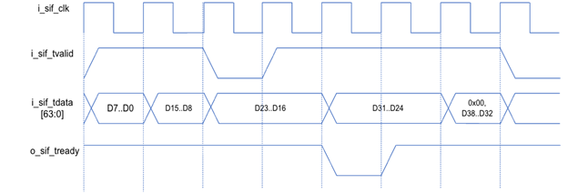
Figure 1 Sensor RX AXI-Streaming Interface
Sensor Event
An event signal for each of the sensor interfaces is available as an input to the Holoscan Sensor Bridge IP.
For example, the sensor event signal can be connected to the front-end sensor PHY error signal to notify the host in the event of a PHY error and for the host to perform a soft reset.
Once sensor event signal is asserted for minimum of one “i_sif_clk”, the Holoscan Sensor Bridge IP will gate receiving AXI-Stream data. The sensor event signal can be de-asserted by hard or software reset. The sensor event signal will also generate and transmit a Control Event packet if the sensor event mask bit is not set.
Streaming data from the Host RX to Sensor TX is not supported in the current IP. An example application for Sensor TX is software-defined radio.
This will be supported in a future IP version.
The Sensor RX data are packetized into UDP packets and transmitted on Host TX AXI-Stream ports.
UDP Overhead
UDP packets require overhead such as headers in the beginning of the packet and iCRC added to the end of the packet. UDP packet overhead is dependent whether the UDP packet is a normal UDP packet or an End of Window UDP packet. UDP packet structures for both are described in a table below.
Normal UDP Packet
Byte Count |
Description |
Byte Size |
Endianess |
|---|---|---|---|
| 0 to 13 | Ethernet Header | 14 | Big Endian |
| 14 to 33 | IPv4 Header | 20 | Big Endian |
| 34 to 41 | UDP Header | 8 | Big Endian |
| 42 to 69 | Holoscan Sensor Bridge Header | 28 | Little Endian |
| 70 to N-101 | Sensor Data | N - 82 | Little Endian |
| N-9 to N-51 | iCRC | 4 | Little Endian |
N=Configured Ethernet Packet Length
End of Window UDP Packet - see section for more information on window
Byte Count |
Description |
Byte Size |
Endianess |
|---|---|---|---|
| 0 to 13 | Ethernet Header | 14 | Big Endian |
| 14 to 33 | IPv4 Header | 20 | Big Endian |
| 34 to 41 | UDP Header | 8 | Big Endian |
| 42 to 73 | Holoscan Sensor Bridge Header | 32 | Little Endian |
| 74 to M-101 | Sensor Data | M - 74 | Little Endian |
| M-9 to M-51 | iCRC | 4 | Little Endian |
M=Remaining sensor bytes at the End of Window + 82 bytes of overhead
The Ethernet, IPv4, and UDP headers abide by the standard Ethernet header format.
Note the Frame Check Sequence (FCS) is the last 4 bytes of the ethernet packet and is part of the ethernet packet length, but it is NOT calculated and added by the Holoscan Sensor Bridge IP. The ethernet IP is expected to calculate and add the FCS to the end of the UDP packet.
The Preamble and Start Frame Delimiter (SFD) are also expected to be added by the Ethernet IP, these fields are not calculated as part of the ethernet packet length.
Sensor Data Throughput
Because of UDP overhead, the total sensor data throughput is less than the maximum ethernet bandwidth available.
Using the reference design ethernet packet length of 1486 bytes, the calculated sensor data throughput is 9.146G, for a 10G ethernet block.
When considering the Preamble, SFD, and Interpacket Gap added per ethernet packet by the Ethernet IP, the total sensor throughput will be reduced.
Note the sensor data throughput is dependent on the ethernet packet length. Smaller ethernet packet length will result in smaller sensor data throughput.
Sensor Data Latency
The Holoscan Sensor Bridge IP will begin packetizing the sensor data into UDP packets once enough sensor data is received to construct a full UDP packet. The latency between the last sensor data of the UDP packet received at the input of the Holoscan Sensor Bridge IP and the first data of the UDP packet transmitted out of the Holoscan Sensor Bridge IP is 50 host interface clock cycles.
This is assuming there is no other transmit packets in queue.
Sensor Window
In certain sensor applications, a window size carries specific purpose. For example, the size of 1 frame in camera sensor application can be the window size.
The Holoscan Sensor Bridge IP is configurable to send an end of window packet at the end of a specified window size. For more details, refer to Holoscan documentation.
The Host RX interface is used for the host to communicate with the FPGA. The host can send BOOTP Response, PING, and Nvidia-defined Ethernet Control Bus (ECB) to read and write FPGA registers.
The Host RX AXI-Stream ports must be connected to the MAC IP RX AXI-Stream ports.
Host RX AXI-Stream ports comply to the AMBA AXI-Stream protocol. TUSER signal indicates a packet error (ex: Frame Check Sequence error). TUSER signal is evaluated only when TLAST is high.
When TUSER is high on the same cycle as TLAST is high, the Holoscan Sensor Bridge IP will drop the entire ethernet packet.