

Dataplane
Dataplane is the flow of data from sensor interface to the host interface and vice versa. AXI-Stream protocol is used to interface to and from the Sensor and Host to the Holoscan Sensor Bridge IP. AXI-Stream is an AMBA defined bus protocol to transfer data between endpoints.
The AXI4-Stream protocol specification documented in revision IHI0051B is used in the Holoscan Sensor Bridge IP.
Bandwidth matching between Sensor and Host is an important consideration of Holoscan
Sensor Bridge integration. Sensor bandwidth must be equal to or less than the Host
bandwidth to avoid backpressure. To match the Host bandwidth, the sensor clock can run
at 156.25 MHz if AXI-S TVALID is high all the time or run at double the clock
frequency and assert AXI-S TVALID every other clock cycle. The Sensor clock can be
asynchronous to Host clock but the effective Sensor bandwidth must be equal to or less
than the Host bandwidth.
Sensor RX (Sensor to FPGA)
In the current version of the Holoscan Sensor Bridge IP, the Sensor RX AXI-Stream signals are constrained as follows:
The full TDATA bus is sent to the host for every TVALID cycle.
TLAST high terminates the current sensor window and includes the data from the TLAST cycle. It is optional for generic streams, but it is recommended when the sensor has a meaningful frame boundary because it re-synchronizes the internal bytes-per-window counter. More information about the sensor window is described later in this page.
The TUSER signal is used in camera applications to indicate long-packet attributes such as embedded data or line end.
TKEEP signals are ignored.
In the future version of the Holoscan Sensor Bridge IP, the expected functionality of the Sensor RX AXI-Stream signals are:
TKEEP signal will indicate valid bytes on TDATA to be transmitted. TKEEP is only valid when TLAST is high.
An example timing diagram of the Sensor RX AXI-Stream is depicted below. This example
uses sensor data size of 39 bytes (DATAPATH_WIDTH=64). D0, D1, and so on in the
diagram represent 1 byte.
Note that in the TLAST clock cycle, the MSB is padded with 0. The padded 0 will be transmitted to the host.
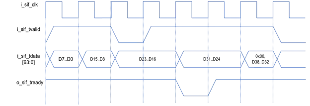
Figure 1 Sensor RX AXI-Streaming Interface
Sensor Window
In certain sensor applications, a window size serves a specific purpose. For example, in a camera sensor application, the number of bytes in one frame can be the sensor window size.
When the end of sensor window is reached, the Holoscan Sensor Bridge (HSB) IP transmits a metadata packet. The metadata packet alerts the host that sensor data buffered in memory is ready to be processed. Refer to the Metadata Packet section for more details.
End of sensor window can occur in two ways.
- The number of received sensor-data bytes reaches the configured sensor window.
i_sif_axis_tlastis asserted.
Ideally, the calculated sensor window size matches the received sensor data size. In the
case they’re different, asserting i_sif_axis_tlast allows for re-synchronization of
sensor window between host and the HSB IP.
If i_sif_axis_tlast is asserted earlier than the calculated sensor window size, a
metadata packet is sent to host with the Flags[0] field asserted to indicate early TLAST
and the internal sensor window resets to 0.
If i_sif_axis_tlast is asserted after the end of window, a metadata packet is first
sent to host for reaching the configured end of window. Another metadata packet is sent
when i_sif_axis_tlast is asserted; that second packet is treated as an early TLAST
condition for the next window.
In an architecture where the frame size is expected to be dynamic, i_sif_axis_tlast
can be used as the primary source of generating the end of frame. In this case, the
window size should be configured to the largest expected value, allowing
i_sif_axis_tlast to always drive the end of window.
The metadata packet has a “Valid Number of Bytes within Buffer” field that can be used to identify the number of bytes transferred in the current sensor window.
Camera Streaming
Although the Holoscan Sensor Bridge’s sensor ports are agnostic to data format, there are situations in which a unified data format is preferable. One specific application is for streaming camera data. For seamless integration with the example IMX274 Holoscan driver, MIPI CSI-2 camera data must be arranged in the following way. This allows for the same drivers to work across different HSB devices.
Users can adopt a different MIPI CSI-2 format than the one listed below, as long as the software driver is also developed to decode the incoming MIPI CSI-2 data. When CoE format is used, follow the CoE pixel format described in the CoE section.
Outside of the use of current software drivers for camera data, there is no restriction on the format of the i_sif_axis_tdata bus.
The Sensor AXI-S interface for MIPI CSI-2 camera data for the IMX274 example is:
- Short MIPI packets must not be streamed to the Sensor AXI-S interface.
- Headers of Long MIPI packets must not be streamed to the Sensor AXI-S interface.
- Footers of Long MIPI packets must not be streamed to the Sensor AXI-S interface.
- Null and blanking packets must not be streamed to the Sensor AXI-S interface.
- Each Long MIPI packet should be aligned to an 8-byte boundary. They can be zero padded if needed.
- Pixel data must remain in the RAW format, for example MIPI RAW10 format.
i_sif_axis_tuser[0]should be asserted during cycles containing embedded data (MIPI Data Type = 0x12).*i_sif_axis_tuser[1]should be asserted on the final clock cycle of a long packet. This is identified as the Line End signal.**i_sif_axis_tlastshould be asserted on the final cycle of a frame when a frame boundary is available.**
*i_sif_axis_tuser signals are used only for high-bandwidth cameras that need internal
Image Signal Processing (ISP). For further details, please contact the NVIDIA Holoscan
team.
**Asserting i_sif_axis_tlast on the final cycle of a frame is optional, but is
highly recommended to re-synchronize on frames if the calculated and actual sensor
window are different. Asserting i_sif_axis_tlast on a Frame End packet requires a
buffer to hold the previous long packet, since the Frame End packet comes some time
after the previous long packet.
An example of formatting IMX274 in 1080p to Sensor RX AXI-S with DATAPATH_WIDTH=8 is
shown below. 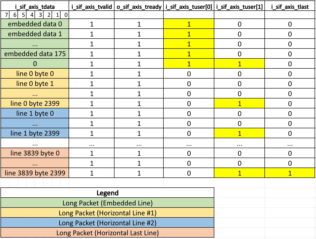
Figure 3 MIPI to Sensor RX AXI-S Packing (DATAPATH_WIDTH=8)
An example of formatting IMX274 in 1080p to Sensor RX AXI-S with DATAPATH_WIDTH=64 is
shown below. 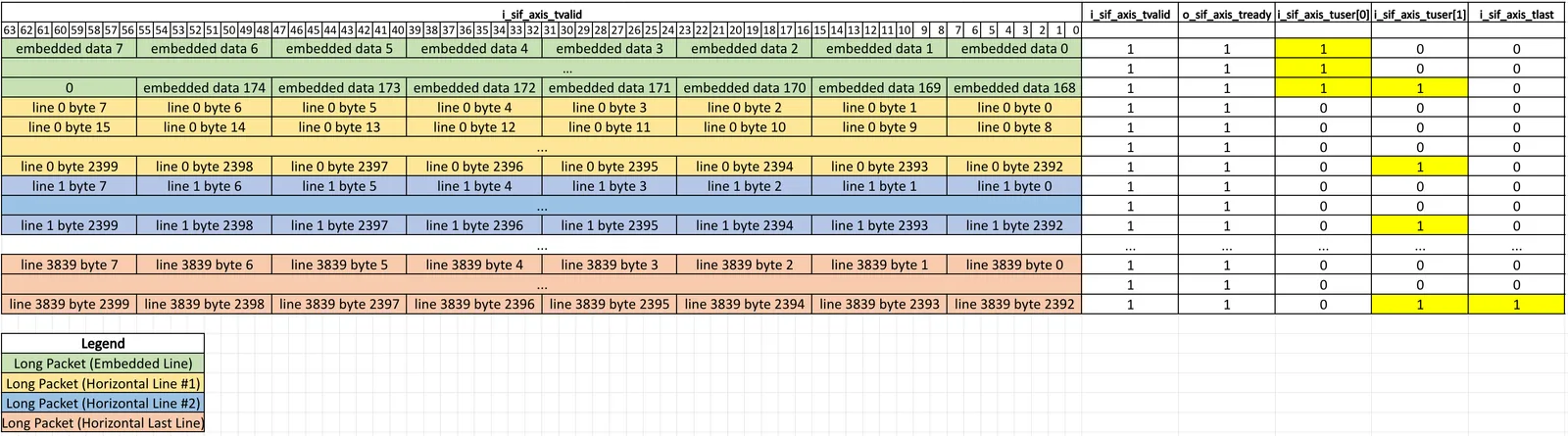
Figure 4 MIPI to Sensor RX AXI-S Packing (DATAPATH_WIDTH=64)
An example sensor window calculation for IMX274 in 1080p, RAW10 mode with
DATAPATH_WIDTH=64 is shown below.
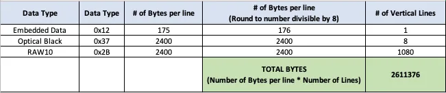
Figure 5 Sensor Window Calculation
Sensor Interface to Virtual Port Mapping
The Holoscan Sensor Bridge IP supports mapping multiple sensor interfaces to virtual
ports for data access. This mapping is controlled by the FPGA parameter SIF_RX_NUM_VP
which defines the number of virtual ports per sensor interface. When not explicitly
configured, SIF_RX_NUM_VP defaults to 1 for all sensors. The virtual port mapping is
only valid when using high bandwidth camera data settings. When high bandwidth camera
data settings are not used, the virtual port setting is undefined and set to 0. Software
interacts with sensor data through these virtual port indices.
The virtual ports are concatenated together in a sequential manner, where each sensor interface’s virtual ports are allocated in order. For example:
- With 2 sensors and
SIF_RX_NUM_VP={1,1}:- Sensor 0’s data is accessible on virtual port 0
- Sensor 1’s data is accessible on virtual port 1
- With 2 sensors and
SIF_RX_NUM_VP={2,2}:- Sensor 0’s data is accessible on virtual ports 0 and 1
- Sensor 1’s data is accessible on virtual ports 2 and 3
Sensor Event
A sensor event signal can be used to generate an interrupt message to the host.
For example, the sensor event signal can be connected to the front-end sensor PHY error signal to notify the host in the event of a PHY error and for the host to perform a soft reset.
In another example, in a camera application, the end of frame can be connected to the sensor event signal so the host can change camera settings between frames.
The interrupt message can be generated on either positive or negative or both edges of the sensor event signal, as configured using the software API. The sensor event signal is crossed into the Host clock domain within the Holoscan Sensor Bridge IP, so the sensor event signal must be asserted for a minimum of 2 Host clock cycles.
Sensor TX (Host to FPGA to Sensor)
The Host can transmit sensor data via RoCE Send packets. The HSB IP strips the network headers and CRC from the RoCE Send packets and forwards the sensor data through the AXI-Stream interface.
Host TX (FPGA to Host)
The Sensor RX data are packetized into Ethernet packets and transmitted on Host TX AXI-Stream ports. There are several different packet formats available.
- Camera over Ethernet (CoE)
- RDMA over Converged Ethernet (RoCE)
- Linux-based UDP sockets
At the end of a sensor window, a metadata packet is sent to notify the host that a sensor frame or window is ready for processing. For RoCE, the metadata packet uses a Write with Immediate operation to generate a host interrupt.
CoE
Camera over Ethernet (CoE) packets are emitted as native Ethernet packets using an IEEE 1722B-style header. Unlike RoCE packets, CoE packets do not include IPv4, UDP, BTH, RETH, or RoCE iCRC fields. The Holoscan Sensor Bridge IP generates a fixed 46-byte Ethernet/CoE header, then appends the sensor payload. The Ethernet MAC is expected to append the Ethernet Frame Check Sequence (FCS).
CoE packetization is selected per sensor path with the is_1722b configuration bit.
When CoE is selected, the packetizer uses the configured host MAC address as the
destination MAC address and the device MAC address as the source MAC address.
The CoE Flags field identifies frame boundaries and threshold crossings:
At the end of a sensor window, the IP can also emit a CoE metadata packet. The CoE metadata packet uses the same 46-byte CoE header, followed by the 48-byte metadata record described below. The metadata packet uses the CoE end-of-frame flag value.
When CoE is used for camera streaming, the payload is expected to follow the CoE pixel
format. The payload must not include MIPI short packets, MIPI long-packet headers,
long-packet CRC bytes, null packets, or blanking packets. Pixel lines are zero padded to
a 64-byte boundary. tuser is unused for CoE and can be driven low, while tlast
should be asserted on the last cycle of a frame. Pixel samples are byte-aligned for ISP
processing; for example, RAW10 is packed as {2'b0, P2[9:0], P1[9:0], P0[9:0]}. If the
incoming stream uses the HSB raw pixel format, the packetizer can convert it to the CoE
pixel format through software configuration.
RoCE
- N = Configured Ethernet packet length or remaining end of sensor window size.
- BTH: Base Transport Header
- RETH: RDMA Extended Transport Header
Linux UDP Based
RoCE (RDMA over Converged Ethernet) is typically associated with specialized hardware and switch support for true zero-copy, low-latency networking. However, even in environments where the network switch or hardware does not natively support RoCE, it is still possible to leverage the RoCE protocol at the software level. In such cases, standard Linux sockets can be used to transmit and receive Ethernet frames that follow the RoCE packet structure. The application or driver can simply parse the relevant RoCE fields, such as the Base Transport Header (BTH), RETH, and other protocol-specific headers, directly from the UDP payload. This approach allows for interoperability and testing of RoCE-based data flows without requiring full hardware offload or switch support, enabling software-based RDMA emulation, protocol development, or integration with custom FPGA or sensor platforms that generate RoCE-formatted packets. While this method does not provide the full performance benefits of hardware-accelerated RDMA, it enables flexible deployment and development in standard Ethernet environments.
Metadata Packet
The Ethernet, IPv4, and UDP headers abide by the standard Ethernet header format.
The RoCE metadata packet is sent at the end of a frame or sensor window. This packet includes metadata about the frame transmission. It follows the RoCE protocol and uses the 0x2B opcode, which generates an interrupt to the Host.
Note the Frame Check Sequence (FCS) is the last 4 bytes of the Ethernet packet and is part of the Ethernet packet length, but it is NOT calculated and added by the Holoscan Sensor Bridge IP. The Ethernet IP is expected to calculate and add the FCS to the end of the packet.
The Preamble and Start Frame Delimiter (SFD) are also expected to be added by the Ethernet IP; these fields are not calculated as part of the Ethernet packet length.
Sensor Data Throughput
Because of packet overhead, the total sensor data throughput is less than the maximum Ethernet bandwidth available.
Using the reference design Ethernet packet length of 1486 bytes, the calculated sensor data throughput is 9.146G, for a 10G Ethernet block.
When considering the Preamble, SFD, and Interpacket Gap added per Ethernet packet by the Ethernet IP, the total sensor throughput will be reduced.
Note the sensor data throughput depends on the Ethernet packet length. Smaller Ethernet packet length will result in smaller sensor data throughput.
Sensor Data Latency
The Holoscan Sensor Bridge IP will begin packetizing the sensor data once enough sensor data is received to construct a full output packet. The latency between the last sensor data of the packet received at the input of the Holoscan Sensor Bridge IP and the first data of the packet transmitted out of the Holoscan Sensor Bridge IP is 50 host interface clock cycles.
This assumes there are no other transmit packets in the queue.
Host RX (Host to FPGA)
The Host RX interface is used for the host to communicate with the FPGA. The host can send BOOTP responses, ICMP echo requests, and NVIDIA-defined Ethernet Control Bus (ECB) packets to read and write FPGA registers.
The Host RX AXI-Stream ports must be connected to the MAC IP RX AXI-Stream ports. Holoscan Sensor Bridge IP Host RX expects the Frame Check Sequence (FCS) to be removed.
Host RX AXI-Stream ports comply to the AMBA AXI-Stream protocol. TUSER signal indicates a packet error (ex: Frame Check Sequence error). TUSER signal is evaluated only when TLAST is high.
When TUSER is high on the same cycle as TLAST is high, the Holoscan Sensor Bridge IP will drop the entire Ethernet packet.