

Hardware Setup
This page covers device setup for Holoscan Sensor Bridge dev kits that have built-in support. For the comprehensive list of supported partner products, please visit the Holoscan Sensor Bridge homepage. Many vendors maintain Holoscan Sensor Bridge ports to their FPGAs, MCUs, and sensor modules. Contact these vendors for instructions on how to use their products.
Lattice CPNX100-ETH-SENSOR-BRIDGE
Microchip MPF200-ETH-SENSOR-BRIDGE
Leopard imaging VB1940 Eagle Camera
TauroTech DA326
The Holoscan Sensor Bridge board
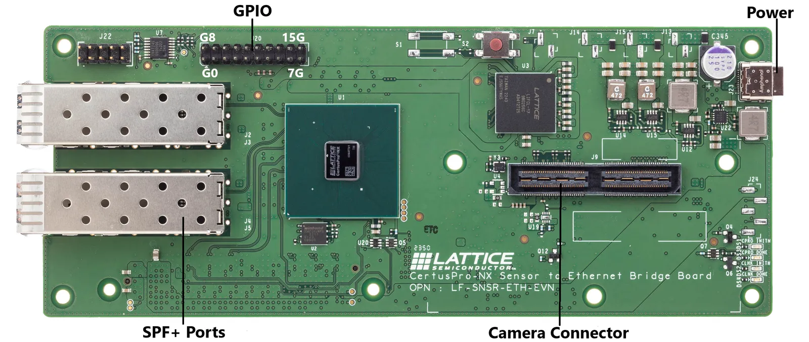
Lattice CPNX100-ETH-SENSOR-BRIDGE has the following connectors:
- SFP+ ports - Two 10Gbps Ethernet ports which connect to the host system.
- Camera connector - This connector is used to interface with a camera (e.g. IMX274).
- Power port - the sensor bridge device is powered by using a USB-C power supply with input voltage from 5V to 20V. Since the sensors are powered through the sensor bridge board, it is recommended to use a dedicated power supply to power both the board and the sensors.
- GPIO pins - the sensor bridge device supports 16 GPIO pins (0…15) and 4 ground pins (marked ‘G’ in the image above).
Note that the sensor bridge device does not provide a USB host interface: the USB-C interface is used only for power. All host interaction is through the Ethernet ports.
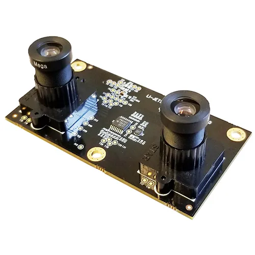
Holoscan sensor bridge reference applications are currently using the IMX274 dual camera module:
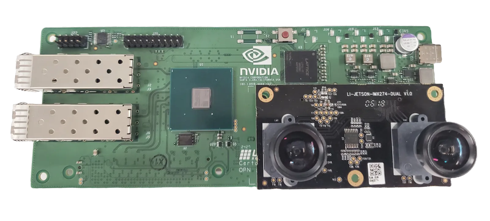
The camera module is mounted on the sensor bridge device in the following manner:
Connecting Holoscan sensor bridge to the Host
-
Make sure the Holoscan sensor bridge board is powered off.
-
Mount the Camera module into the camera connector as shown in the above image.
-
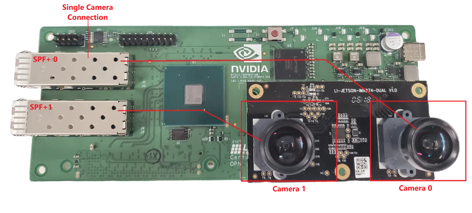
Connect the SFP+ port marked “SFP+ 0” in the image below to the host system. This is the appropriate connection for accessing the first camera in a stereo camera pair. This port provides access to the data from the camera indicated by “Camera 0”.
- For IGX Devkit, connect to the QSFP port marked with red arrow in the image below.
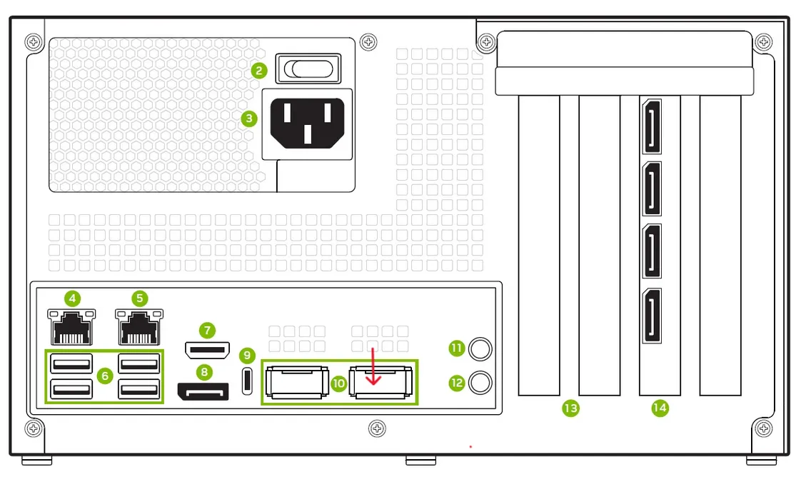
For configurations using the second camera in the stereo camera pair, connect the SFP port labelled “SFP+ 1” to the unconnected QSFP port on the back of IGX.
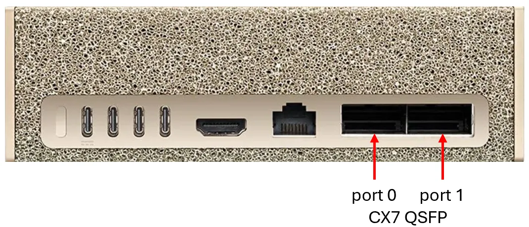
- For DGX Spark, connect the “SFP+ 0” port on the HSB to the “CX7 QSFP port 0” shown below. For configurations using the second camera in the stereo camera pair, connect the “SFP+ 1” port on the HSB to the “CX7 QSFP port 1”.
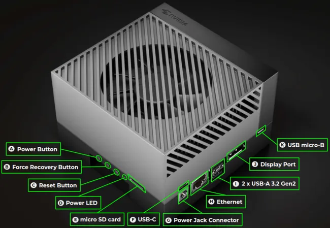
- For AGX Orin Devkit, connect to the 10G Ethernet port (marked ‘H’ in the image below).
-
Connect a USB-C power supply with a minimum of 12V/2A to the USB-C power connector of the sensor bridge device and wait for the green LEDs on the sensor bridge board to light up.
-
For more details see the Lattice CPNX100-ETH-SENSOR-BRIDGE
Follow the instructions in the setup page to configure your host system.