

PTP Application Note
The Holoscan Sensor Bridge (HSB) IP supports Precision Time Protocol (PTP) version 2 per IEEE1588-2019 specification.
PTP synchronizes the host time to all downstream devices. To enable the host as the Time Transmitter and send PTP packets, refer to the Host Setup page.
The HSB IP’s PTP instantiation can be removed by defining EXT_PTP (meaning External
PTP) in the “HOLOLINK_def.svh”. Defining EXT_PTP will expose different I/Os to the HSB
IP to input the external PTP timestamp to HSB IP. Refer to
Port Description for more information. Important note is that
“i_pps” port needs to be toggled once a second when EXT_PTP is defined. Enumeration
with host happens through BOOTP messages which is triggered by PPS.
Use Case
ß Synchronized PTP time can be used to:
- Timestamp specific Sensor Interface and Host Interface events. Refer to Metadata Packet for PTP timestamp events transmitted to the host.
- Synchronize multiple HSBs on the network.
- In camera application, a synchronized Vertical SYNC (VSYNC) strobe can align the start of exposure across multiple cameras on the network. For more information, refer to VSYNC
Profile
HSB IP supports the following PTP profiles
- 1588 profile with End to End Delay Mechanism (default)
- gPTP profile with Peer to Peer Delay Mechanism
- 1588 profile with Peer to Peer Delay Mechanism
HSB IP PTP implementation is limited to:
- Operate as PTP Receiver only
- Transmit and Receive PTP messages over Ethernet L2 Layer only.
- Does not support Announce messages.
- Does not support Best Master Clock Algorithm. It assumes there is only 1 master in the network at a given time.
- PTP traffic can only occur on HSB IP Host Interface 0.
PTP Flow
PTP Message and Timestamps
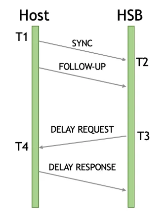
- Timestamp 1 (T1) Host broadcasts it’s current time by sending SYNC and FOLLOW-UP (in 2-step mode) messages.
- Timestamp 2 (T2) HSB stamps it’s current time when it received the SYNC message.
- Timestamp 3 (T3) HSB sends Delay Request message upon receiving SYNC/FOLLOW-UP message. (For End to End Delay Mechanism)
- Timestamp 4 (T4) Host stamps it’s current time upon receiving the Delay Request message and sends a Delay Response message.
With 4 timestamps available, HSB IP can calculate the Offset Measurement (OFM) and Mean Delay.
Peer to Peer delay mechanism has different PTP messages and timing but it’s concept of mean delay measurement is similar.
PTP message flow with End to End delay mechanism is shown below.
PTP Timer
PTP module runs in “i_ptp_clk” domain. “i_ptp_clk” can be asynchronous to the “i_hif_clk” domain but for best performance, generate the clock derived from the recovered Ethernet PCS or MAC clock. Recommended PTP clock frequency is from 95MHz to 105MHz.
PTP Timer sequence:
- Following reset, timer begins at 0 seconds and 0 nanoseconds. At each rising clock
edge, the timer increments by (1/
PTP_CLK_FREQ) nanoseconds and 24-bit fractional nanoseconds, wherePTP_CLK_FREQis a parameter defined in “HOLOLINK_def.svh” For example in 10G application,PTP_CLK_FREQ=100446545derived from recovered Ethernet PCS clock and the incremental value per rising clock edge is 9.955ns. - When PTP is enabled, the HSB IP latches the Host Timestamp (T1) as it’s current time and the timer and continues to increment as before. This allows the timer to catch up to the current PTP time.
- In subsequent SYNC messages, uses the timestamps (T1-T4) to calculate the Offset Measurement (OFM) and adjust the timer’s incremental value. Adjusting the incremental value (inverse of frequency) compensates for on-board oscillator drift and temperature variation.
Offset Measurement
Offset Measurement (OFM) is the time offset between host time and HSB IP time. When the Host time (T1) arrives at HSB IP, the timestamp is outdated by factors such as mean delay, switch residence time, and delay asymmetry. Adjusting the OFM for the various delays calculates a more accurate offset for more accurate synchronization.
- Mean Delay
- Mean Delay is defined as the average network delay from Host to HSB and from HSB to Host. Mean Delay samples are further averaged in a moving window to smooth outlier values.
- Switch Residence Time
- The network connection between Host and HSB can be a direct connection or through numerous switches to aggregate multiple HSB into a single host. Each switches in the network adds residence time, or time it takes for the PTP message to traverse through the switch. This residence time is appended to the PTP message in the Correction Field.
- Delay Asymmetry
- Delay Asymmetry is defined as the time difference between the Ingress and Egress of
Ethernet packets. The delay asymmetry within HSB IP is automatically calculated.
HOST_WIDTHparameter can affect the number of clock cycles it takes to consume the PTP message which adds to the Ingress delay. - There is also the delay asymmetry outside of the HSB IP in the FPGA vendor Ethernet MAC and PCS IP. This is vendor specific and is programmable using the PTP Delay Asymmetry register.
- Delay Asymmetry is defined as the time difference between the Ingress and Egress of
Ethernet packets. The delay asymmetry within HSB IP is automatically calculated.
Frequency Adjustment Digital PLL (DPLL)
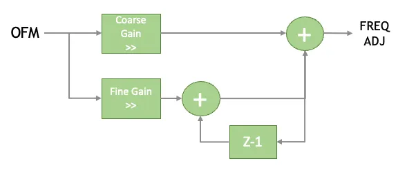
The Offset Measurement (OFM) feeds the Digital PLL (DPLL), which produces a frequency adjustment value. In the timer, that adjustment is applied as a correction to the per-clock increment so the closed loop tracks host time. Coarse Gain and Fine Gain are programmable registers: each scales OFM by an arithmetic right shift.
Registers
Below lists the configurable PTP registers.
Below lists the Status PTP Registers.
An example python script to reconfigure PTP is shown below. The values used in the example are the default configuration after reset.
Performance
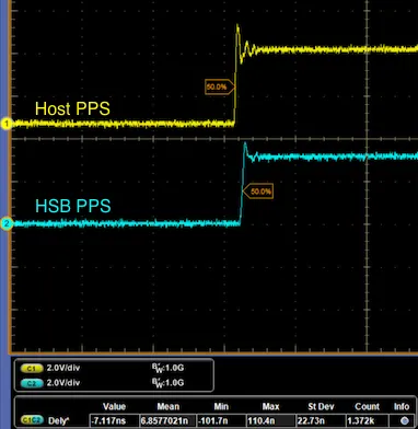
The performance of the PTP was tested by comparing the Pulse Per Second (PPS) between the host and the HSB IP on oscilloscope.
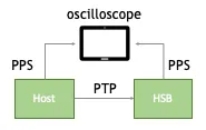
The performance test was done with the following configuration.
Oscilloscope capture of the PPS measurement is shown below.
Debug
- PTP Status [0] = 0, [1] = 0
- SYNC/FOLLOW-UP message not received.
- Check on Wireshark if host is transmitting PTP messages.
- If host is transmitting PTP messages but HSB is not transmitting any PTP messages,
check the MajorSdoID field of the host PTP packet.
- For 1588 profile, MajorSdoID should be 0.
- For gPTP profile, MajorSdoID should be 1.
- SYNC/FOLLOW-UP message not received.
- PTP Status [0] = 1, [1] = 0
- SYNC/FOLLOW-UP message received but HSB IP PTP is not enabled.
- PTP Status [0] = 1, [1] = 1
- PTP is enabled and successfully received PTP messages.
- OFM
- Read OFM register in quick succession. If the Frequency Adjustment DPLL is stable, OFM should stabilize near 0 between -100 and +100. If the OFM is oscillating and magnitude is growing, the DPLL could be unstable, increase the Coarse Gain and Fine Gain registers.
VSYNC
In camera application, Vertical SYNC (VSYNC) or sometimes referred to as Frame SYNC (FSYNC), controls the start of camera exposure for that frame. Multiple cameras connected across multiple HSBs can be synchronized to a single host via PTP. From synchronized PTP time, VSYNC can be generated to synchronize the start of frame capture.

VSYNC RTL Integration
Reference design “vsync_gen” RTL module can generate VSYNC strobes based on the current timestamp. Ports of the “vsync_gen” module are listed below.
The “vsync_gen” module can be instantiated at the same wrapper module of the HSB IP where the APB signals connect to the HSB IP APB signals. The base address of the VSYNC module will depend on which bit of the HSB IP’s “o_apb_psel” port is connected. Refer to Register Interface page for more information. In the Lattice CPNX100-ETH-SENSOR-BRIDGE reference design, “vsync_gen” module is connected to HSB IP’s “o_apb_psel[6]” which maps to 0x7000_0000 base address.
VSYNC Register Configuration

- Configure Frequency mode, Delay, Start Val, and Exposure time.
- Delay and Exposure time should be set to a value less than the period of the configured frequency.
- Some cameras use the active state (Exposure Time register) of VSYNC signal as the exposure time of the camera.
- Enable VSYNC
- Once enabled, VSYNC is generated at the start of next Pulse Per Second (PPS) signal.
GPIO MUX Enable
GPIO MUX Enable register is used to force route the VSYNC signal to an existing GPIO. When routing the VSYNC signal to a tri-state HSB GPIO, tri-state should be the final assignment to ensure the synthesis tool places the GPIO to an INOUT buffer. Example code to route VSYNC signal onto tri-state GPIO:
In Lattice CPNX100-ETH-SENSOR-BRIDGE reference design, PPS and VSYNC signals is muxed out to few GPIOs. Bits to force PPS and VSYNC signals are listed below.