

Clocking and Reset
Clocking
There are 4 main clocks in the system, host interface (HIF), APB interface, sensor interface (SIF), and PTP interface clocks.
The Host Interface signals connect to transmit or receive data from the Ethernet MAC. Therefore, the Host Interface bandwidth (clock frequency x data width) should support the Ethernet bandwidth of the design.
For example, when integrating the Holoscan Sensor Bridge IP in 10G application, a common clock frequency and data width used is 156.25MHz and 64 bits respectively. If the system Ethernet MAC outputs a 156.25MHz, a possible design is to use the same Ethernet MAC output clock as the Host Interface clock. If the system cannot use the Ethernet MAC clock directly, then a dual clock FIFO can be used to match the bandwidth of the Ethernet MAC. Ultimately, the clock architecture is determined by the intended application and FPGA vendor used for the Holoscan Sensor Bridge IP.
The Sensor Interface clocks (i_sif_rx_clk and i_sif_tx_clk) drives the frontend sensor AXI-Stream interface. Each sensor AXI-Stream interface has a dedicated clock input that can operate at an independent frequency.
The sensor AXI-Stream signals are crossed into the Host Interface clock domain using a dual clock FIFO within the Holoscan Sensor Bridge IP.
Resets
The Holoscan Sensor Bridge IP outputs resets synchronous to respective clocks from 1 main asynchronous reset input.
The input reset port (i_sys_rst) is an active-high, asynchronous reset. This port should be connected to the board reset pin (RESET, active-high, in the diagram) gated with the PLL locked signal. This will assert the reset to the Holoscan Sensor Bridge IP until the PLL is locked.
Example connection of the input and output resets are shown below.
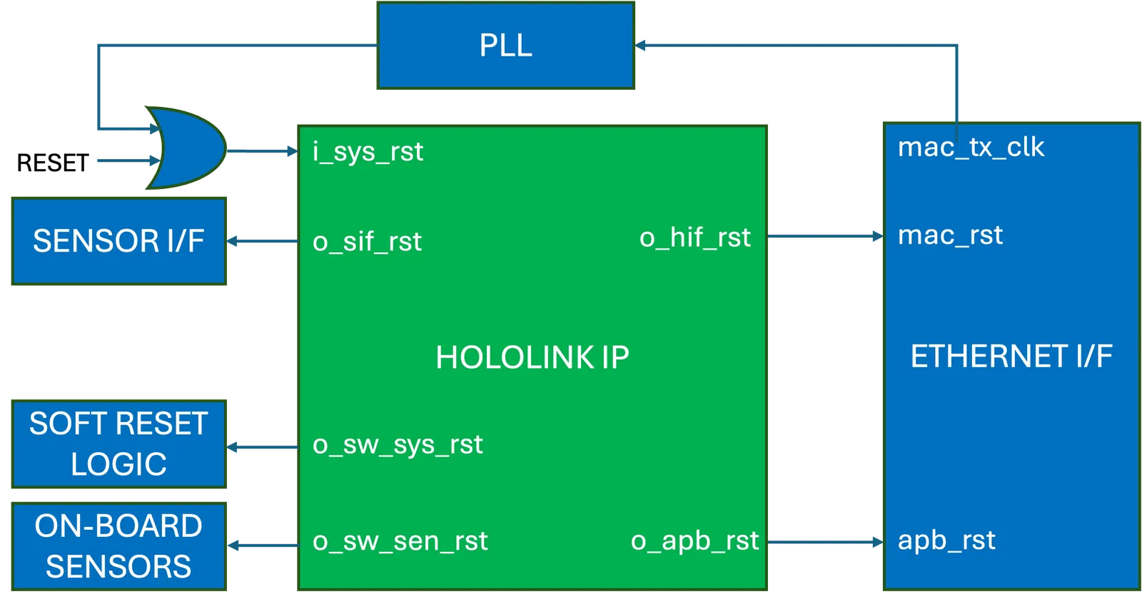
Figure 1 Reference Design Reset Connections
Table below describes the various output resets and its clocking relations when asserting and deasserting.
Table 1 Reset Assertion and Deassertion
- N=
SENSOR_RX_IF_INST, M=SENSOR_TX_IF_INST