

Host Setup
Holoscan sensor bridge is supported on the following configurations:
- IGX systems configured with IGX OS 1.1.2+ with CX7 SmartNIC devices.
- AGX Orin systems running JP6.2.1+. In this configuration, the on-board Ethernet controller is used with the Linux kernel network stack for data I/O; all network I/O is performed by the CPU without network acceleration.
- AGX Thor systems running JP7.2 with MGBE SmartNIC device and CoE transport.
- DGX Spark systems running DGX OS 7.2.3+ with CX7 SmartNIC devices.
- x86 Linux workstations with an NVIDIA discrete GPU. Two host receive paths are supported: unaccelerated Linux socket-based receivers (used primarily for development or testing purposes) and an accelerated RoCE path that requires a ConnectX network adapter on the link to the sensor bridge. Note that this configuration is not part of the primary reference platforms; GPUDirect RDMA into GPU memory on the RoCE path may appear available from the GPU and driver even when the PCIe path on the host does not support it, in which case you must disable GPU VRAM frame buffers at build time (see the x86 Linux tab).
After the Holoscan sensor bridge board is set up, configure a few prerequisites in your host system. While holoscan sensor bridge demonstration applications usually run in a container, these commands are all to be executed outside the container, on the host system directly. These configurations are remembered across power cycles and therefore only need to be set up once.
-
Install git-lfs
Some data files in the Holoscan sensor bridge source repository use GIT LFS.
-
Grant your user permission to the docker subsystem:
Reboot the computer to activate this setting.
Next, follow the directions on the appropriate tab below to configure your host system.
IGX
AGX Orin
DGX Spark
AGX Thor
x86 Linux
-
Update the GPU driver to 535.309.01 and install IGX 1.1.3 by running the following.
Reboot the machine so the new driver loads:
After rebooting, confirm the new driver is active:
-
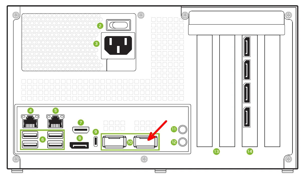
Determine the name of the network device associated with the first CX7 port. This is the rightmost QSFP port when looking at the back of the IGX unit.
This will produce a list of CX7 ports; your device names may vary. The lowest numbered
one, in this case roceP5p3s0f0, is the first CX7 port.
Check the CX7 firmware version using one of the devices names that appear on your machine from the command above.
If the version is 28.38.1026 or lower, please download the appropriate “ConnectX-7 Firmware” iso and upgrade the CX7 firmware. Make sure to reboot the machine and re-check the firmware has loaded to the newer one.
Assign the name of the first CX7 port to the variable $IN0.
Next, determine which host ethernet port is associated with that device, and assign that
to the variable $EN0, which we’ll use later during network configuration.
In summary, the host network interface associated with $IN0 (roceP5p3s0f0) is $EN0
(enP5p3s0f0np0); your specific device names may vary.
- IGX OS uses NetworkManager to configure network interfaces. By default, the sensor
bridge device uses the address 192.168.0.2 for the first port. Set up your first
ethernet device (
$EN0) to use the address 192.168.0.101 with a permanent route to 192.168.0.2 using the recommended MTU for use with RoCE: (Here is more information about configuring your system if you cannot use the 192.168.0.0/24 network in this way.)
Apply power to the sensor bridge device, ensure that it’s properly connected, then
ping 192.168.0.2 to check connectivity:
- The second SFP+ connector on the sensor bridge device is used to transmit data acquired from the second camera on a stereo camera module (like the IMX274). By default, the sensor bridge device uses the address 192.168.0.3 for that second port. Connect the second IGX QSFP port (indicated with the red arrow below) to the second SFP+ port on the sensor bridge device.
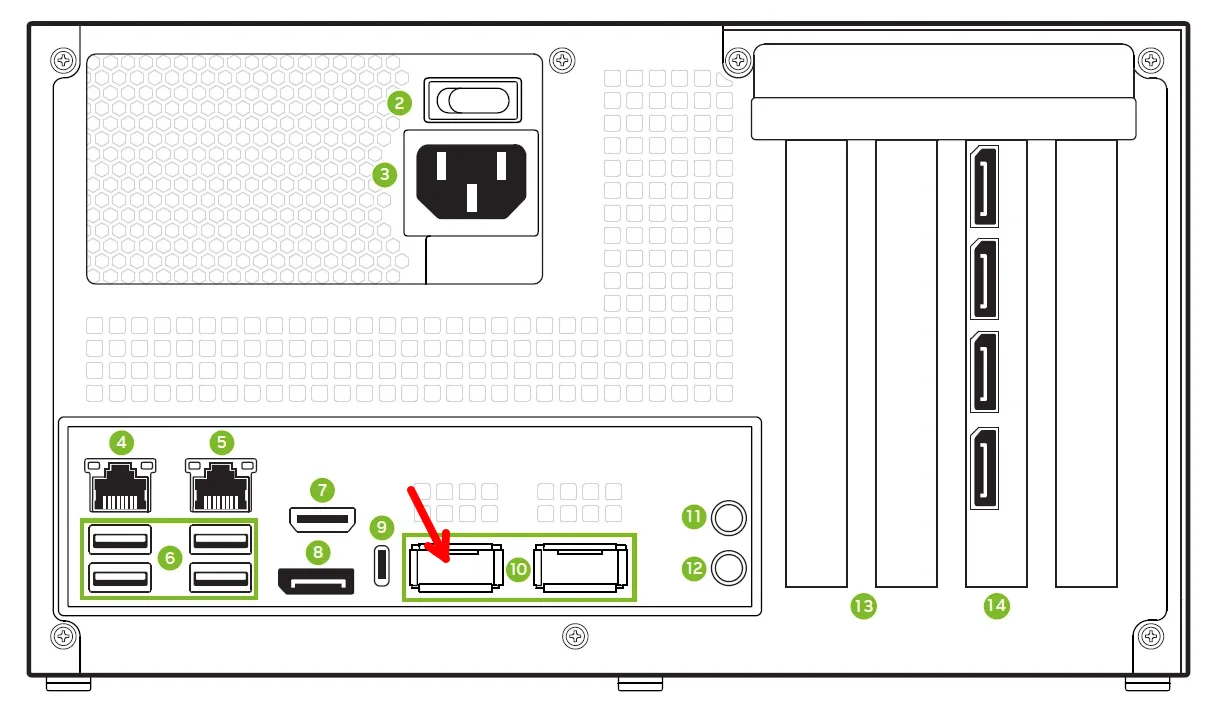
Let’s refer to these as $IN1 and $EN1. Given the commands to assign $IN0 and
$EN0 above,
As above, your device names may be different. Configure the second QSFP network port with an appropriate address and permanent route:
Now test the second connection with ping 192.168.0.3:
When the second port is configured, the first port should continue to respond to pings as appropriate.
Now, for all configurations,
-
Configure the network receiver buffer for running unaccelerated network examples: Holoscan sensor bridge supports running Li VB1940, IMX274, and TauroTech DA326 Hawk using unaccelerated network Linux sockets. For best performance of these examples increase the Linux sockets network receiver buffer:
-
Make sure that $EN0 is set to the name of the Ethernet controller connected to HSB. Some installations require reboots which will clear this value, so be sure and configure it appropriately for your configuration per the instructions above.
-
Enable PTP on $EN0. This synchronizes the timestamps reported with received data with the host time.
Run the
phc2systool at boot time. This synchronizes the clock in $EN0 with the system clock. First, install thelinuxptptool.Next, set up a systemd service file that will run
phc2sys.Configure it for execution at startup, and start it now.
Next, run ptp4l to send PTP SYNC messages to $EN0.
Set up a systemd service file for this.
Finally, run it.
-
For Orin iGPU with Cuda 12 configurations only (Jetpack 6 and IGX 1.X): Install NVIDIA DLA compiler. Applications using inference need this at initialization time; some OS images for iGPU don’t include it.
-
Log in to Nvidia GPU Cloud (NGC) with your developer account:
-
If you don’t have a developer account for NGC please register at https://catalog.ngc.nvidia.com/
-
Create an API key for your account: https://ngc.nvidia.com/setup/api-key
-
Use your API key to log in to nvcr.io:
-
Now proceed to build and test the Holoscan Sensor Bridge container.